Reinforcing steel bar banding mechanical arm

A technology for tying steel bars and manipulators, which is applied in construction, building construction, and processing of building materials, etc., can solve the problems of high intensity of manual labor, large workload, and low production efficiency.

Inactive Publication Date: 2008-08-13
于双庆
View PDF0 Cites 12 Cited by
  • Summary
  • Abstract
  • Description
  • Claims
  • Application Information

AI Technical Summary

Problems solved by technology

[0002] In the prior art, the known technology is that the workers hold the binding iron hook and the previously cut iron wire section by section to complete the binding of the steel bars. Some steel cage bindings also need to be completed by two or more people. ...

Method used


Image

  • Reinforcing steel bar banding mechanical arm
  • Reinforcing steel bar banding mechanical arm

Examples


Embodiment Construction

[0009] In order to clearly illustrate the technical features of the solution, the solution will be described below through a specific implementation mode combined with the accompanying drawings.

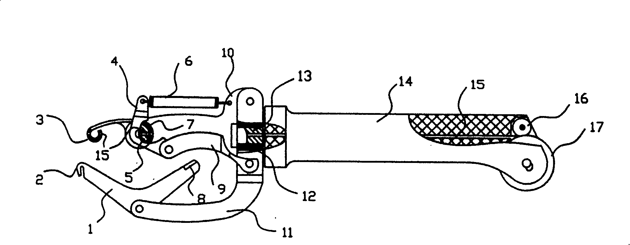
[0010] As can be seen from the accompanying drawings, the steel bar binding manipulator of this program has a handle (14) with a wire guide hole (15), and there are pressure wheels (16) on both sides of the wire guide hole (15) at one end of the handle (14). ) and wire walking wheel (17), the bottom of this wire walking wheel (17) protrudes outside the handle (14). The other end of the handle (14) is fixedly connected with the rotating shaft (13) with the guide wire hole (15) with the handle (14), and the shaft seat (13) that can rotate around the rotating shaft (13) is covered with the rotating shaft (13). 12), a crank arm (11) is fixed on one side of the shaft seat (12), the top of the crank arm (11) is hinged with a V-shaped broken wire swing bar (1), and the broken wire swing bar...


PUM


Abstract

The present invention provides a technical scheme for tying the mechanical hand with the reinforcing steel bar, the scheme of the invention is characterized in that a handle with a thread-guiding hole is provided, two sides of the thread-guiding hole at one end of the handle are provided with a pressure roller and a wire moving wheel; at the other end of the handle a rotating shaft with a thread-guiding hole is fixed with the handle, the rotating shaft is sleeved with a axle base which can rotate around the rotating shaft, one side of the axle base is fixed with a connecting arm with a top hinged with a V-shaped abruption thread swing lever, the top of one arm at the outside of the abruption thread swing lever is arranged with a wire drawing hook, and the top of the other arm of the abruption thread swing levier is arranged with a wire abruption shifting block; the other side of the axle base is fixed with a fixing frame which is arranged with a wire disconnecting mechanism and a thread-knitting machine with a thread-guiding hole. The scheme can be operated with one hand and the tying quality can be guaranteed, the production efficiency can be increased more than four to seven times, the scheme can adapt any working environment and working surface and is used for replacing the mechanical hand which is manipulated by hand.

Description

Technical field: [0001] The invention relates to a construction machine, in particular to a steel bar binding manipulator for binding steel bars for building steel cages. Background technique: [0002] In the prior art, the known technology is that the workers hold the binding iron hook and the previously cut iron wire section by section to complete the binding of the steel bars. Some steel cage bindings also need to be completed by two or more people. Not to mention the high intensity of manual labor, the production efficiency is extremely low, and the workload of steel bar binding used in general cast-in-place steel-concrete structure buildings accounts for 25-40% of the total engineering volume, which is a huge workload. The construction industry has experienced decades of technological changes, and various related construction machinery have been greatly improved and developed, but the steel bar binding process is still in the most primitive technical state. This situati...

Claims


Application Information

Patent Timeline
IPC IPC(8): E04G21/12
Inventor 于双庆
Owner 于双庆
Why Eureka
Try Eureka