Aluminum electrolysis bath anode arrangement scheme
A technology of aluminum electrolytic cells and configuration schemes, which is applied in the field of aluminum production by molten electrolysis, can solve the problems of increasing workload and loss outweighing the gain, and achieve the effect of reducing the area of the middle seam and achieving considerable economic benefits
- Summary
- Abstract
- Description
- Claims
- Application Information
AI Technical Summary
Problems solved by technology
Method used
Image
Examples
Embodiment 1
[0016] Example 1 300KA aluminum electrolytic cell
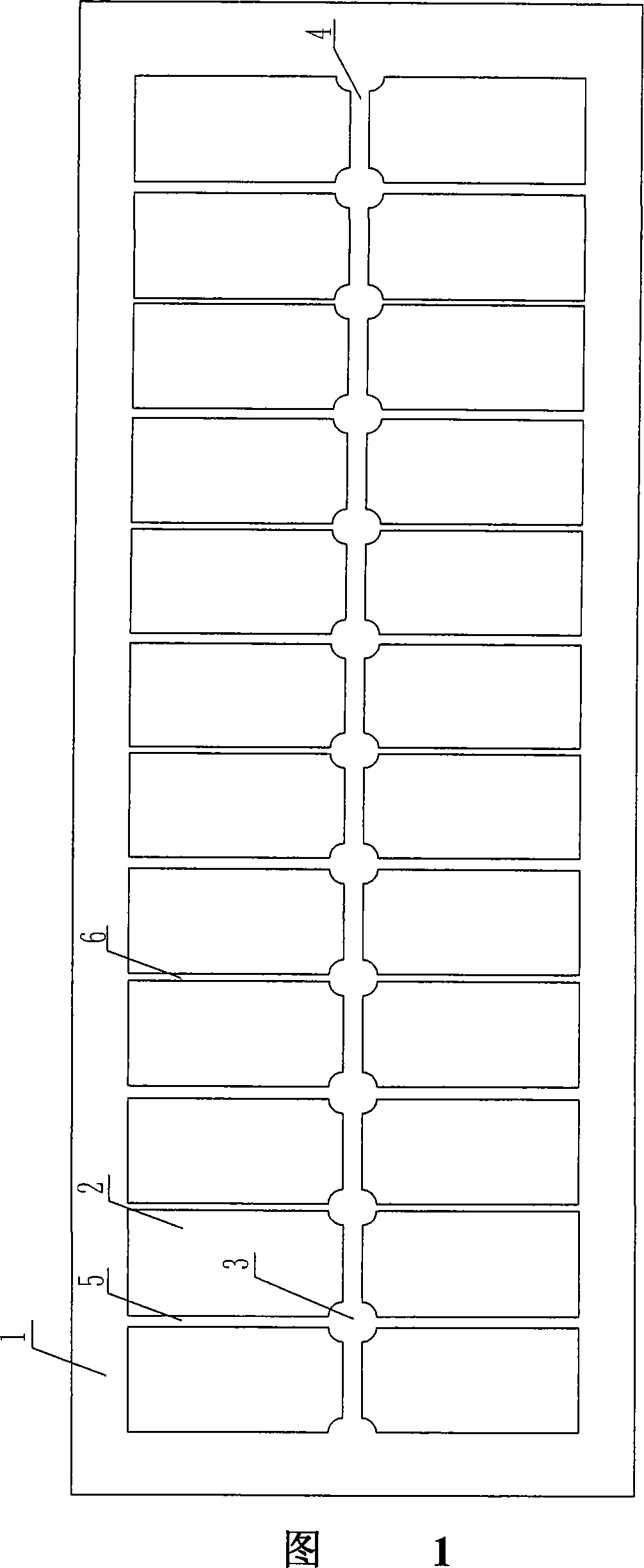
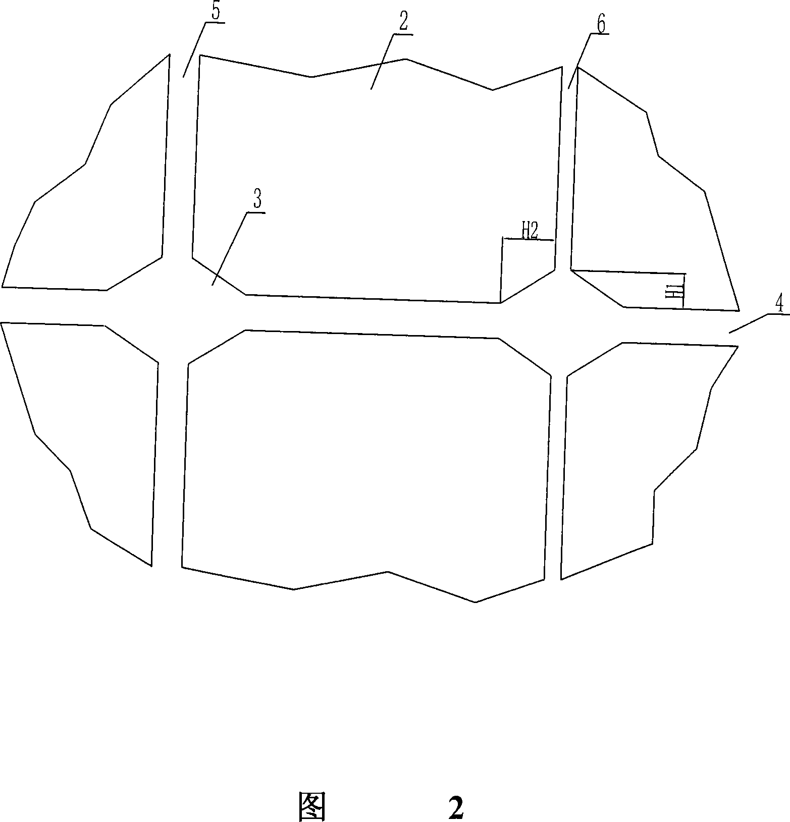
[0017] For the 300KA aluminum electrolytic cell, as shown in Figure 1 and 2, the length (L) of the molten pool is 13080-14350 mm, and the width (W) is 3550-4200 mm; there are 32-44 anode carbon blocks in total, which are divided into two rows Set in the molten pool, each block has a length (La) of 1500-1700 mm and a width (Wa) of 600-700 mm. The distance (W1) between the outer end of the carbon block and the side of the molten pool of the electrolytic tank is 250-350 mm, and the distance (L1) from the outer side of the carbon block near the aluminum outlet and the end of the flue to the side of the molten pool is 300-500 mm. The gap width (W2) between two rows of carbon blocks is 50-100 mm; and the gap between two adjacent carbon blocks in the same row is provided with 4 feeding points, and the feeding point (L2) is 30-50 mm; The feeding point (L3) is 20-30 mm. An isosceles right-angled triangle with a waist length (H1, H2)...
Embodiment 2
[0018] Example 2 360KA aluminum electrolytic cell
[0019] For the 360KA aluminum electrolytic cell, it is roughly the same as that of Embodiment 1, as shown in Figures 1 and 2. Among them, L is 15400-16800 mm; W is 3650-4300 mm. There are 36-48 anode carbon blocks in the whole electrolytic cell, which are divided into two rows and arranged in the molten pool of the electrolytic cell, where La=1550-1750 mm; Wa=650-750 mm. Set 6 feeding points, other parameters are: W1=250-350 mm; W2=50-100 mm; L1=300-500 mm; L2=30-60 mm; L3=20-50 mm. The lengths of the two waists of the truncated right-angled triangle at the end of the anode are respectively: H1=50 millimeters; H2=100 millimeters.
Embodiment 3
[0020] Example 3 400KA aluminum electrolytic cell
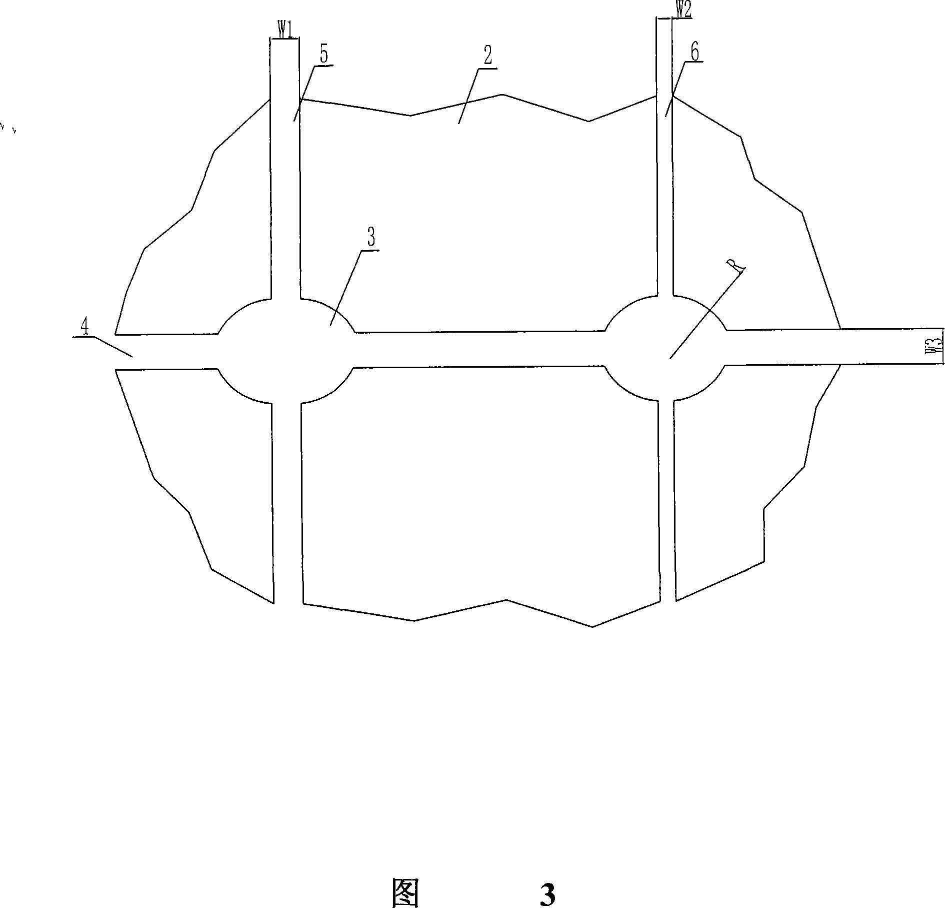
[0021] Same as the above two embodiments, for the 400KA aluminum electrolytic cell, as shown in Figures 1 and 3, L=16100-18150 mm; W=3650-4300 mm. There are 40-52 anode carbon blocks in the whole electrolytic cell, which are divided into two rows and arranged in the molten pool of the electrolytic cell, where La=1550-1750 mm; Wa=650-750 mm. Set 8 feeding points, other parameters are: W1=250-350 mm; W2=50-100 mm; L1=300-500 mm; L2=30-60 mm; L3=20-50 mm. The truncated portion of the anode end is fan-shaped with a radius of 80-150 mm.
[0022] More examples can also be cited. Although their specific parameters are different, they all adopt the method of cutting off two corners at one end of the anode carbon block, which not only reduces the gap between the carbon blocks; Space for feeding points. Experiments have proved that the scheme of the present invention is not only simple and easy to implement, but also has remarkable ...
PUM
 Abstract
Description
Claims
Application Information
 - R&D
- Intellectual Property
- Life Sciences
- Materials
- Tech Scout
- Unparalleled Data Quality
- Higher Quality Content
- 60% Fewer Hallucinations
Browse by: Latest US Patents, China's latest patents, Technical Efficacy Thesaurus, Application Domain, Technology Topic, Popular Technical Reports.
© 2025 PatSnap. All rights reserved.Legal|Privacy policy|Modern Slavery Act Transparency Statement|Sitemap|About US| Contact US: help@patsnap.com


