
Visual sense prosthesis image processing device and method

An image processing device and image processing technology, applied in the field of biomedical engineering, can solve the problems of large volume, unfavorable image quality processing, high power consumption, and achieve the effects of easy connection and communication, improved image quality, and enhanced contrast.

Inactive Publication Date: 2008-08-13
SHANGHAI JIAO TONG UNIV
View PDF1 Cites 41 Cited by
  • Summary
  • Abstract
  • Description
  • Claims
  • Application Information

AI Technical Summary

Problems solved by technology

Its disadvantages are: (1) CCD sensor is used as the image acquisition device. It is difficult for CCD sensor to integrate the driving circuit, signal processing circuit and imaging array in a single chip. , the application in visual prostheses is not conducive to aesthetics and convenience; (2) The CCD sensor is a passive acquisition, and an external voltage must be applied to move the charge in each pixel to the transmission channel, and this external voltage usually requires 12-18V, so the CCD also There must be more sophisticated power line design and withstand voltage strength, and the high driving voltage makes the power consumption of CCD much higher than that of CMOS sensors; (3) the patent lacks image pre-correction function, and the image quality is not conducive to the back-end processing; (4) ) does not take into account the self-regulation function of the visual prosthesis implanter; (5) there is no systematic and perfect image processing strategy

Method used


Image

  • Visual sense prosthesis image processing device and method
  • Visual sense prosthesis image processing device and method

Examples


Embodiment Construction

[0028] The embodiments of the present invention are described in detail below in conjunction with the accompanying drawings: this embodiment is implemented on the premise of the technical solution of the present invention, and detailed implementation methods and specific operating procedures are provided, but the protection scope of the present invention is not limited to the following the described embodiment.

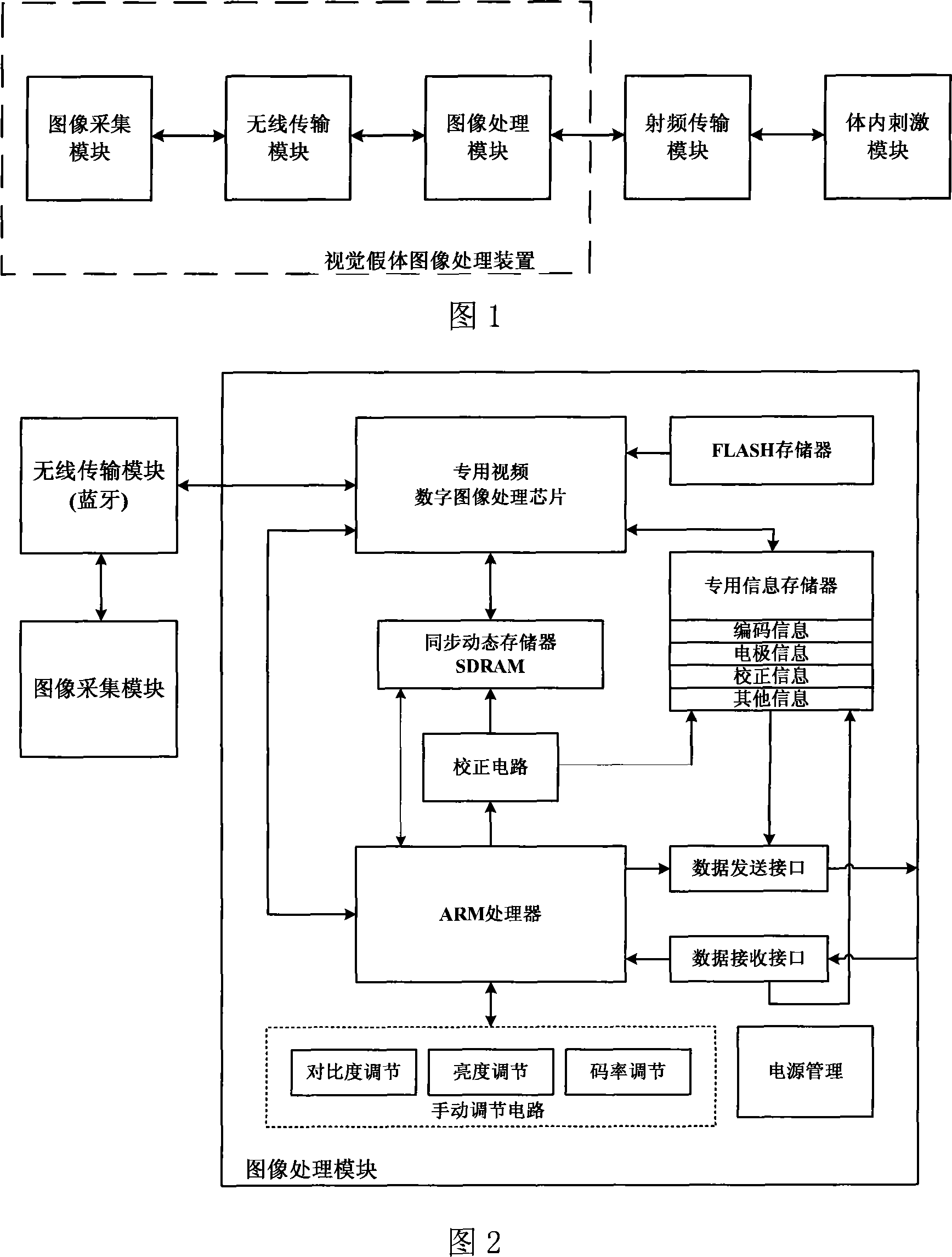
[0029] As shown in Figure 1, the external image information is acquired first through the image acquisition module, and the acquired image information is input into the image processing module through the wireless transmission module, and the image information is simplified, segmented, enhanced, encoded, etc. processed by DSP in the image processing module , the processed image information is output to the image processing module and transmitted to the internal electrode stimulation module through the radio frequency transmission module.

[0030] As shown in Figure 2,...


PUM


Abstract

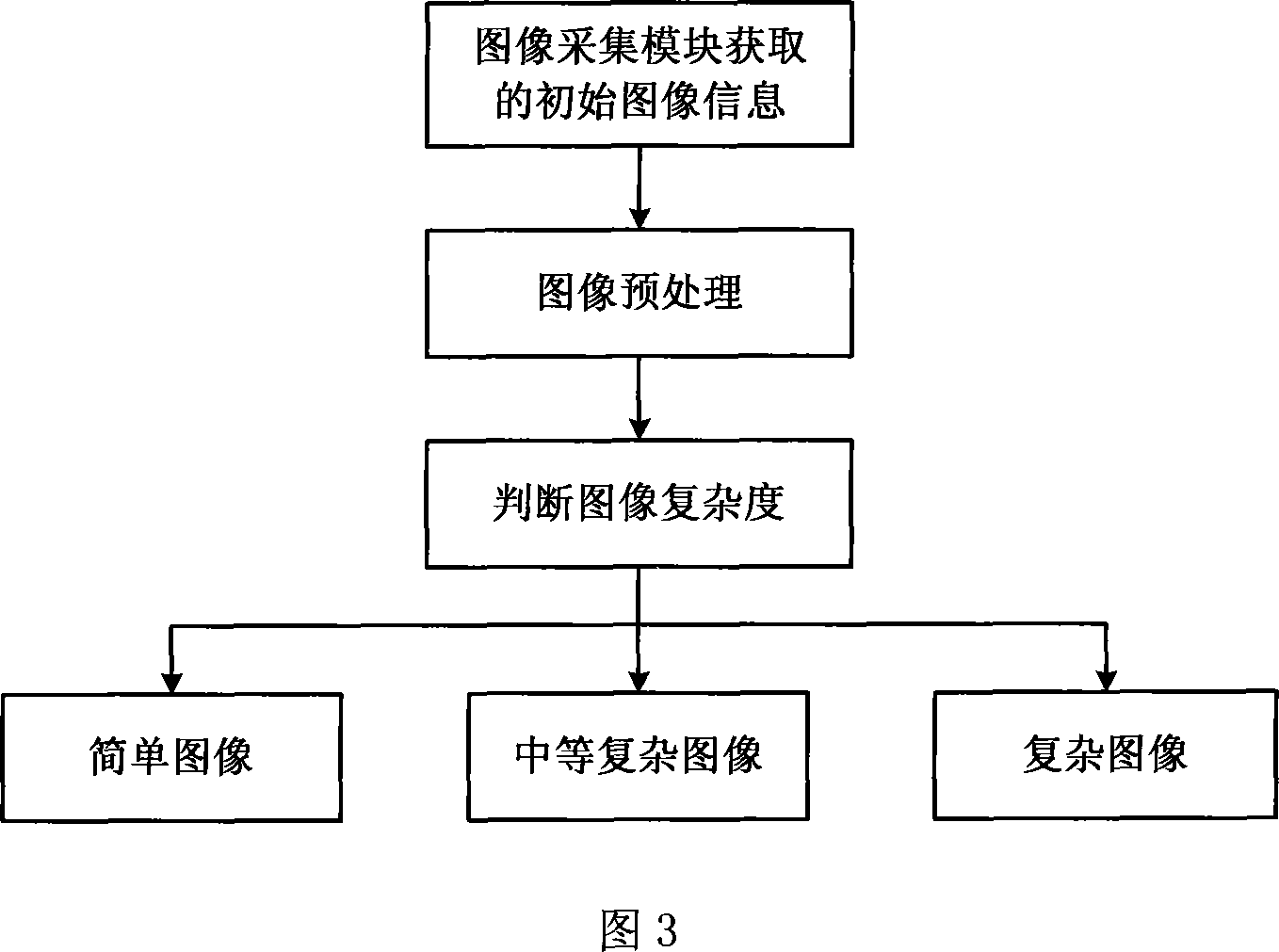
The invention relates to a visual false body image processing device and the method, belonging to the field of biological engineering. In the invention, an image collecting module is a CMOS digital image sensor which converts the obtained image information into digital mode; a wireless transmission module is responsible for the communication of the image collecting module and the image processing module, then transmits the image information collected by the image collecting module to the image processing module; the image processing module has an image information precorrection to the obtained image to improve the image quality, having image information simplifying, strengthening or coding treatment to transform the obtained image information into the pulse encouraging mode accepted by the visual system to provide for an internal stimulation module, and providing the function of self regulation for users. The method is showed as follows: firstly executing image pretreatment, then through an image complexity judgment, the image is divided into three kinds and the corresponding treatment procedure is adopted. The invention resolves the prior disadvantage to be applied in all types of visual false body.

Description

technical field [0001] The invention relates to a device and method in the technical field of biomedical engineering, in particular to a visual prosthesis image processing device and method. Background technique [0002] At present, scientists and technicians in many countries are studying the use of visual prostheses to restore the visual function of the blind. A visual prosthesis is an artificial organ that uses electrical stimulation of the visual nervous system to restore vision to the blind. Corresponding stimulation mode; transmit energy and signals to the stimulator implanted in the body and its microelectrode array, and the microelectrode array stimulates nerve cells on the visual pathway to produce phosphenes. Whether it is a retina stimulating visual prosthesis, a visual cortex stimulating visual prosthesis, or an optic nerve stimulating visual prosthesis, a visual image processing system needs to be included. The visual prosthesis is composed of two parts in vit...

Claims


Application Information

Patent Timeline
IPC IPC(8): A61F2/14A61F9/00A61N1/05A61N1/36G06K9/36G06T1/20
Inventor 柴新禹赵瑛田宇坤赵冀任秋实
Owner SHANGHAI JIAO TONG UNIV
Learn More