Chilled-mirror type dew point instrument control method

A control method and technology of dew point meter, applied in the direction of electric controller, material water content, etc., can solve the problems of too thin frost layer, heat accumulation at the hot end of the cold pump, system oscillation, etc.

Inactive Publication Date: 2008-08-06
丁五行 +1
View PDF0 Cites 10 Cited by
  • Summary
  • Abstract
  • Description
  • Claims
  • Application Information

AI Technical Summary

Problems solved by technology

However, the above two methods are difficult or impossible to measure the dew point in some special cases, such as working in a high temperature environment or measuring low humidity gas or measuring low humidity gas in a high temperature environment and system oscillation caused by improper human operation
The main cause of system oscillation is: although the formation of the mirror frost layer is positively correlated with the temperature of the cold end of the cold pump, there is a certain hysteresis
When the frost layer is too thick, the cold pump will be cut off, the temperature of the cold end will rise rapidly, the gas passing through the mirror is very dry, and the speed of water molecules condensing on the mirror is lower than the speed of escaping from the mirror, and the frost layer will become thinner; although When the frost layer is about to reach a certain thickness, the current recovers quickly, but because the mirror surface temperature cannot be lowered quickly, the frost layer will become too thin or even disappear
At this time, the cold pump starts to force the cooling quickly, and the mirror surface quickly condenses the frost layer, which again causes the dew frost layer to be too thick, and the cycle repeats
Especially in high temperature environment, due to the accumulation of heat at the hot end of the cold pump, it is difficult to dissipate, the cooling capacity of the cold pump gradually decreases, and sometimes it is even difficult to cool the cold end to a temperature lower than the dew point again, and the dew point is difficult or impossible to measure

Method used


Image

  • Chilled-mirror type dew point instrument control method
  • Chilled-mirror type dew point instrument control method

Examples


Embodiment Construction

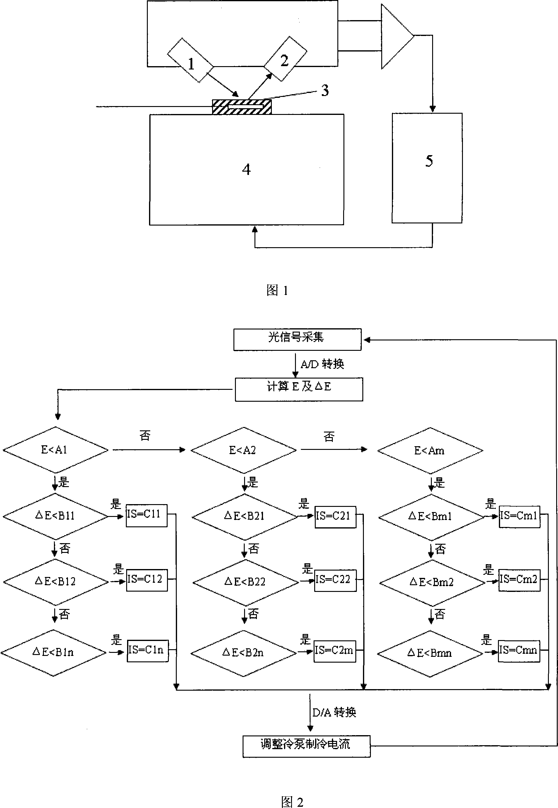
[0013] Figure 1 is a schematic cross-sectional view of the dew point measurement chamber of the chilled mirror dew point meter. The luminous tube 1 emits light, and the cold pump 4 cools down. The thickness of the frost layer on the mirror surface 3 affects the light energy received by the receiving tube 2 . This method is a method of controlling the current of the cold pump 4 step by step after performing data calculation by the processor 5 so as to accurately control the temperature of the mirror surface 3 to control the thickness of the frost layer.

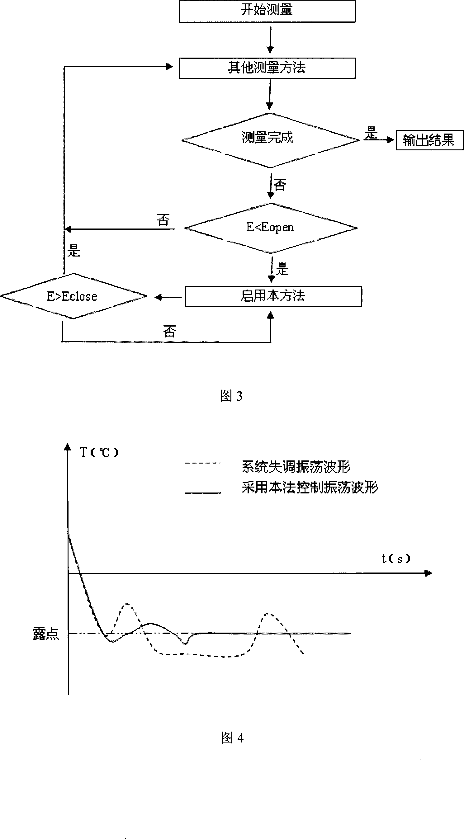
[0014] Fig. 2 and Fig. 3 show the flow diagram of this method to control the current step by step and the flow diagram when it is used in combination with other measurement methods. The light energy reflected or scattered by the photoelectric sensor receiving tube 2 senses the light energy reflected or scattered by the frost layer and outputs an electrical signal, and the processor, etc. The electrical signal converted by A / D ...


PUM


Abstract

A cold mirror type dew point instrument is used to measure the dew point. Under the conditions of a high-temperature operational environment or measuring low-humidity gas or measuring low-humidity gas in a high-temperature environment or manual misoperation, a system oscillation will be caused by system control maladjustment and consequently the dew point is hard to be measured or can not be measured. The control method provided by the invention can set a corresponding current regulation step length according to the luminous energy deviation or the different intervals of luminous energy deviation change ratio in the process of dew elimination, regulate the size of the refrigeration current through adding or deducting a current value equal to the step length to the present refrigeration current to control the mirror surface temperature for controlling the thickness of a frost layer, and consequently the luminous energy is enabled to gradually approach a target value. That is to say, the frost layer on the mirror surface gradually approaches the specific thickness, thereby eliminating the oscillation brought about by the system control maladjustment. The method can finely adjust and control the thickness of the mirror surface frost layer during dew elimination, thereby avoiding the system oscillation or stopping the system oscillation, and realizing the dew point measurement which is hard to be realized or can not be realized in the prior art.

Description

technical field [0001] The invention relates to a control method of a chilled mirror dew point meter, more specifically, a method for eliminating system oscillation caused by control imbalance in the chilled mirror dew point meter. Background technique [0002] The principle of dew point measurement by chilled mirror dew point meter is as follows: a beam of light source is irradiated on the planed mirror surface which can control the temperature, and the reflected light is received by the receiving tube of photoelectric sensor. When the mirror surface is clean and dry, its reflected light is the largest, that is, the emitted light is 100% reflected and received by the photoelectric sensor receiving tube. When the condensed water forms a frost layer on the mirror surface, the emitted light is scattered, so that the intensity of the received reflected light is weakened. The received signal is amplified and then sent to the processor through A / D conversion. After calculation, ...

Claims


Application Information

Patent Timeline
Patent Type & Authority Applications(China)
IPC IPC(8): G01N25/68G05B11/32
Inventor 丁五行李宝明曾峥嵘李卓然杭志峰
Owner 丁五行
Why Eureka
Try Eureka