
Locomotive wheel hoop fastening ring-binding method

A technology of snap rings and tires, applied in mechanical equipment, furnace types, furnaces, etc., can solve problems such as poor hardenability, unsatisfactory plasticity and toughness, insufficient snap ring elasticity, etc., and achieve the effect of increasing radial elasticity

Inactive Publication Date: 2008-08-06
CRRC QINGDAO SIFANG CO LTD
View PDF0 Cites 7 Cited by
  • Summary
  • Abstract
  • Description
  • Claims
  • Application Information

AI Technical Summary

Problems solved by technology

[0003] The snap ring used for the pre-installation of the existing rim, after being fastened to the groove of the rim, has insufficient elasticity in the diameter direction of the snap ring, which makes the snap ring easy to rotate and move up and down in the groove. Therefore, the axial positioning performance of the snap ring for the wheel core is poor
[0004] In addition, the existing clasp material selection is not reasonable, such as general alloy steel and carbon steel in the high temperature setting process, the hardenability of the clasp material is poor, so the plasticity and toughness are not ideal
[0005] The deficiencies in the above prior art are comprehensively reflected in the fact that the positioning performance between the snap ring and the wheel core is difficult to meet the design and use requirements

Method used


Image

  • Locomotive wheel hoop fastening ring-binding method
  • Locomotive wheel hoop fastening ring-binding method
  • Locomotive wheel hoop fastening ring-binding method

Examples


Embodiment 1

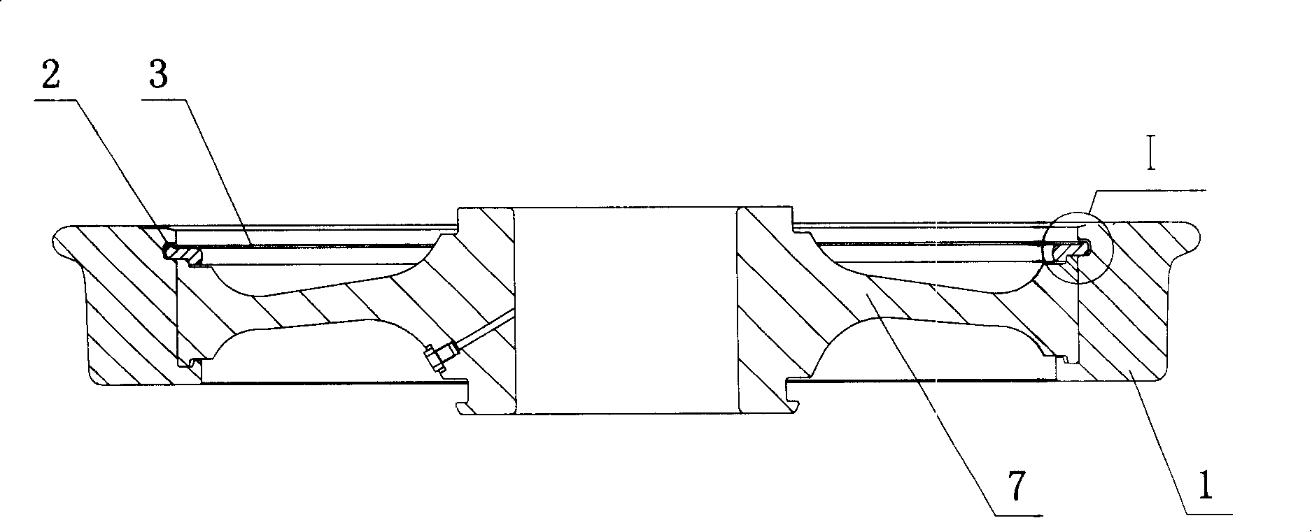
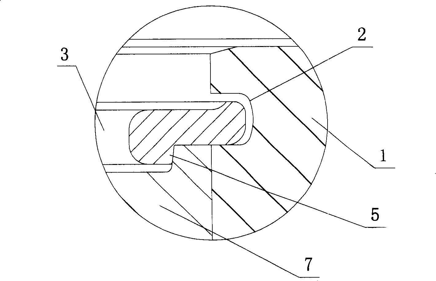
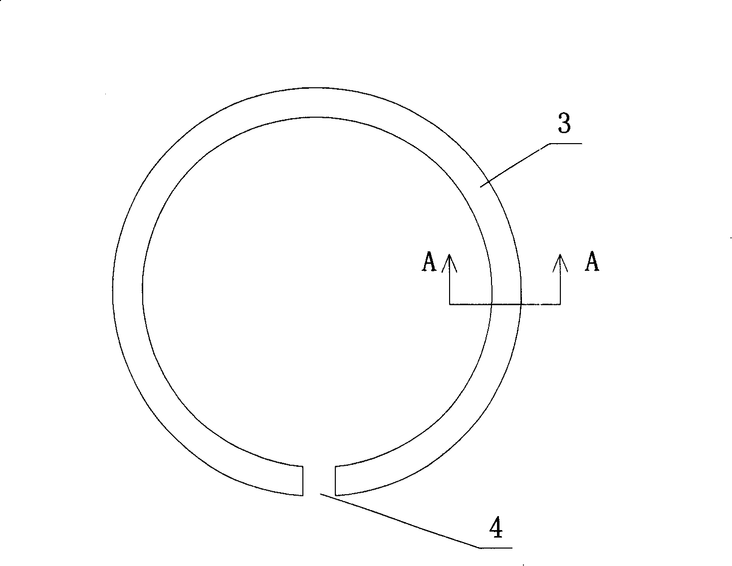
[0035] Example 1, such as Figure 1 to Figure 4 As shown, the snap ring 3 is used for the pre-assembly of the wheel tire 1 of the rail vehicle. After the tire 1 is heat-fitted on the wheel core 7, the snap ring 3 is snapped into the groove 2 of the tire 1, and the snap ring 3 realizes the axial positioning of the wheel core 7 by virtue of its elasticity in the diameter direction.

[0036] In the method for mounting the snap ring on the wheel rim of the motorcycle, before the snap ring 3 is fastened inside the groove 2 of the wheel rim 1, it is processed by a heat-setting process, and the process flow is as follows:

[0037] First, the snap ring 3 is fixedly installed on the heat setting fixture;

[0038] Then, tempering and heating the snap ring 3 with a medium temperature fire within the range of 420-500°C, so that the snap ring 3 can be shaped on the fixture;

[0039] Secondly, the snap ring is continuously tempered and heated within the above temperature range for 4 hours...


PUM

PropertyMeasurementUnit
angleaaaaaaaaaa

Abstract

The invention relates to a method for buttoning a retainer ring for a locomotive wheel band, which improves the processing technology, materials and the structure which affect retainer ring radial elasticity to intensify elastic parameters of the retainer ring on the diameter direction and to increase the buttoning compact degree between the retainer ring and a wheel core. The method comprises: sleeving the wheel band which is heated and slightly expanded on the wheel core and then buttoning the retainer ring in a groove inside the wheel band. The retainer ring is a ring-shaped body with an opening part and the retainer ring adopts the heat setting process to manufacture before the retainer ring is buttoned in the wheel band groove. The procedures of the heat setting manufacturing process comprises: firstly, fixedly installing the retainer ring on a heat setting clamp, then, adopting medium temperature fire with the temperature range of 420DEG C-500DEG C to temper and heat to enable the retainer ring to shape on the clamp, then, continuingly tempering and heating the retainer ring in the temperature range for 3-5 hours, and lastly taking the retainer ring after tempering from the heat setting clamp.

Description

technical field [0001] The invention relates to a method for fastening snap rings used in the assembly of rail vehicle wheels, which belongs to the field of mechanical manufacturing. Background technique [0002] The rail vehicles currently in use, such as internal combustion engines or electric locomotives, urban light rail and subways, etc., have a bogie that is a rigid frame that fixes the front and rear wheel sets. The axial positioning between the snap ring and the wheel core is realized by fastening the snap ring on the tire. [0003] The snap ring used for the pre-installation of the existing rim, after being fastened to the groove of the rim, has insufficient elasticity in the diameter direction of the snap ring, which makes the snap ring easy to rotate and move up and down in the groove. Therefore, the axial positioning performance of the snap ring for the wheel core is relatively poor. [0004] In addition, the material selection of the existing snap rings is unr...

Claims


Application Information

Patent Timeline
Patent Type & Authority Applications(China)
IPC IPC(8): C21D9/40C21D1/26C21D11/00B23P11/02F16B21/18
Inventor 姜建东孔令明王文来
Owner CRRC QINGDAO SIFANG CO LTD
Learn More