Passive microwave multiplexor and demultiplexer

A multiplexer, microwave filter technology, used in waveguide-type devices, circuits, multi-terminal-pair networks, etc.

Inactive Publication Date: 2008-07-30
MITSUBISHI ELECTRIC CORP
View PDF2 Cites 7 Cited by
  • Summary
  • Abstract
  • Description
  • Claims
  • Application Information

AI Technical Summary

Problems solved by technology

Therefore, an interconnection network without any (or at least minim

Method used


Image

  • Passive microwave multiplexor and demultiplexer
  • Passive microwave multiplexor and demultiplexer
  • Passive microwave multiplexor and demultiplexer

Examples


Embodiment Construction

[0028] In the microwave field of the present invention, different technologies can be applied: stripline, microstrip or coplanar technology. Striplines are conductive wires embedded in a dielectric and / or magnetic substrate covered by a ground plane on the back and top sides of the substrate. Microstrip lines are also wires, but they are attached to the top side of a dielectric and / or magnetic substrate, and only the back side of the substrate is capped with a ground plane. In coplanar technology, a ground plane surrounds the wire, and sometimes the backside of the substrate is covered with a ground plane. Although the present invention is primarily described with respect to microstrip technology, it is understood that it is not limited thereto, and also includes any embodiments implemented by stripline and coplanar technology.

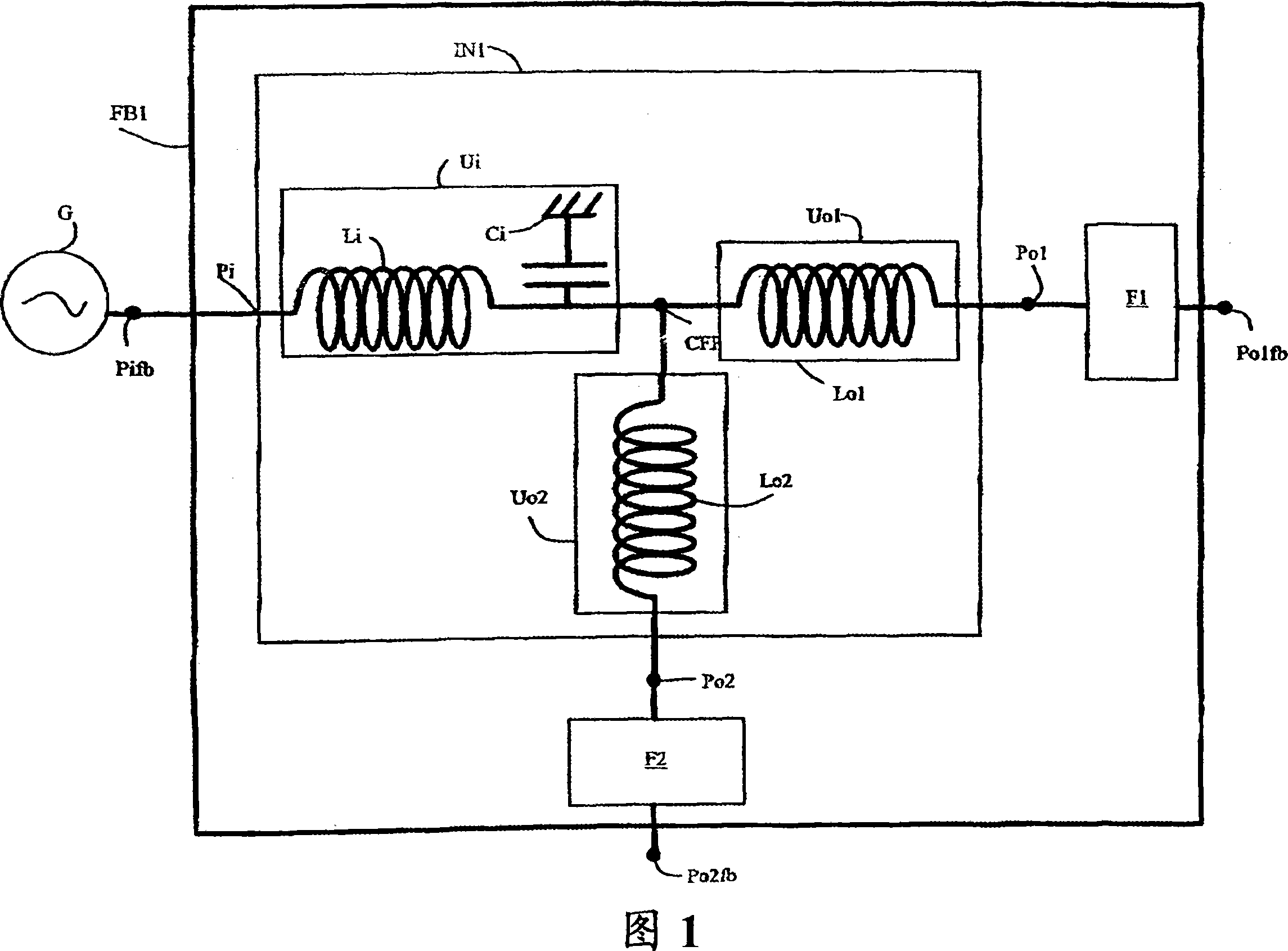
[0029] Fig. 1 schematically shows a microwave filter bank FB1 according to a first embodiment of the present invention. The microwave filter bank F...


PUM


Abstract

The present invention relates to a microwave filter bank intended to be used either as or a multiplexer or de-multiplexer in a UWB-type system, said microwave filter bank including a plurality of filters and an interconnection network both connecting a first port (Pifb) of said microwave filter bank to other ports of said microwave filter bank. Said microwave filter bank is characterised in that said interconnection network includes a plurality of inductors, one of said inductors (Li), said first, has one of its extremities directly connected to said first port (Pifb) and its second extremity connected to the ground through a capacitor (Ci), said first, intended to minimize the effect of the reflection response of the microwave filter bank in its operating sub-bands without degrading its transmission response, said first inductor (Li) and capacitor (Ci) being intended to provide a nearly constant total admittance at said first port of said microwave filter bank for the operating band of each of said filters, each of other inductors, said second, is intended to provide a good in-band matching of the response of one of said filters with a targeted response.

Description

technical field [0001] The present invention relates to a microwave filter bank intended to distribute electromagnetic energy from an input port to a plurality of output ports, and conversely combine electromagnetic energy from a plurality of output ports to an input port, depending on the frequency of the input signal. The invention also relates to a transceiver of the UWB (Ultra Wideband) type using such at least one microwave filter bank acting as energy splitter (demultiplexer) or energy combiner (multiplexer) . Background technique [0002] A microwave filter bank is generally a device designed to distribute electromagnetic energy from an input port to multiple output ports, and conversely combine electromagnetic energy from multiple output ports to input ports, depending on the frequency of the input signal. For example, such a filter bank can be used as an energy divider when a signal in a frequency band propagates from an input port to an output port that passes onl...

Claims


Application Information

Patent Timeline
IPC IPC(8): H01P5/16H01P5/12H01P1/20
CPCH03H7/46H01P1/213
Inventor S·马尔戈尔
Owner MITSUBISHI ELECTRIC CORP
Why Eureka
Try Eureka