Disk drive and calibration method therefor

A disk drive device and actuator technology, which is applied in the direction of driving/moving recording heads, support heads, instruments, etc., can solve problems such as actuator oscillation, and achieve the effect of suppressing instability

Inactive Publication Date: 2008-07-30
HITACHI GLOBAL STORAGE TECH NETHERLANDS BV
View PDF0 Cites 12 Cited by
  • Summary
  • Abstract
  • Description
  • Claims
  • Application Information

AI Technical Summary

Problems solved by technology

Velocity control through a correction process using an incorrect α may cause actuator oscillations

Method used


Image

  • Disk drive and calibration method therefor
  • Disk drive and calibration method therefor
  • Disk drive and calibration method therefor

Examples


Embodiment Construction

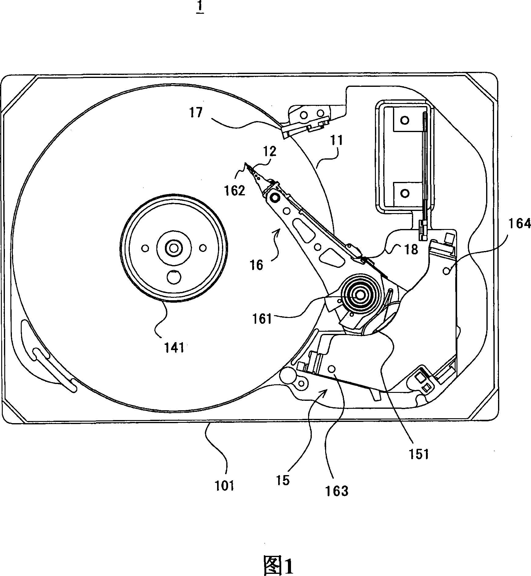
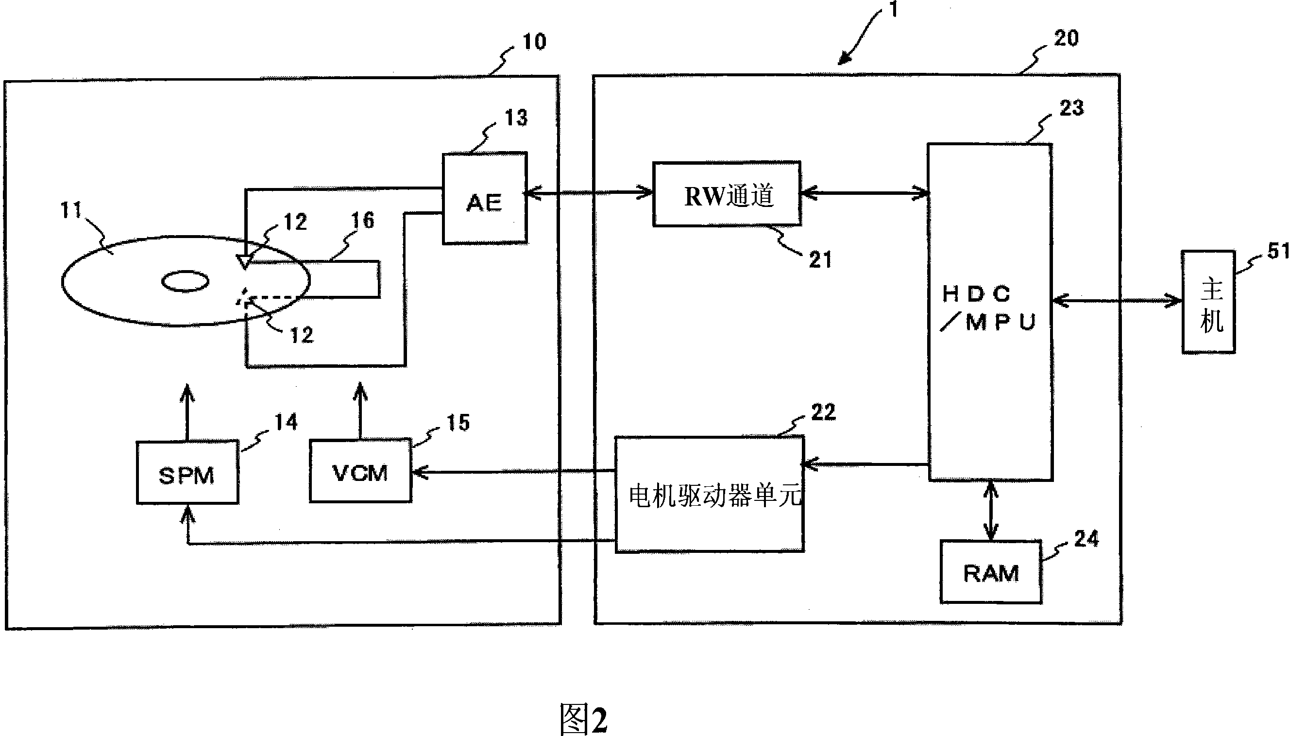
[0039] Hereinafter, preferred embodiments to which the present invention is applied are described. For clarity of explanation, the following description and drawings contain appropriate omissions and simplifications. In all the drawings, the same elements are denoted by the same reference numerals, and their repeated descriptions are omitted if not necessary for clarity of explanation. Next, preferred embodiments of the present invention will be described by taking an example of a hard disk drive (HDD) as an example of a disk drive device.

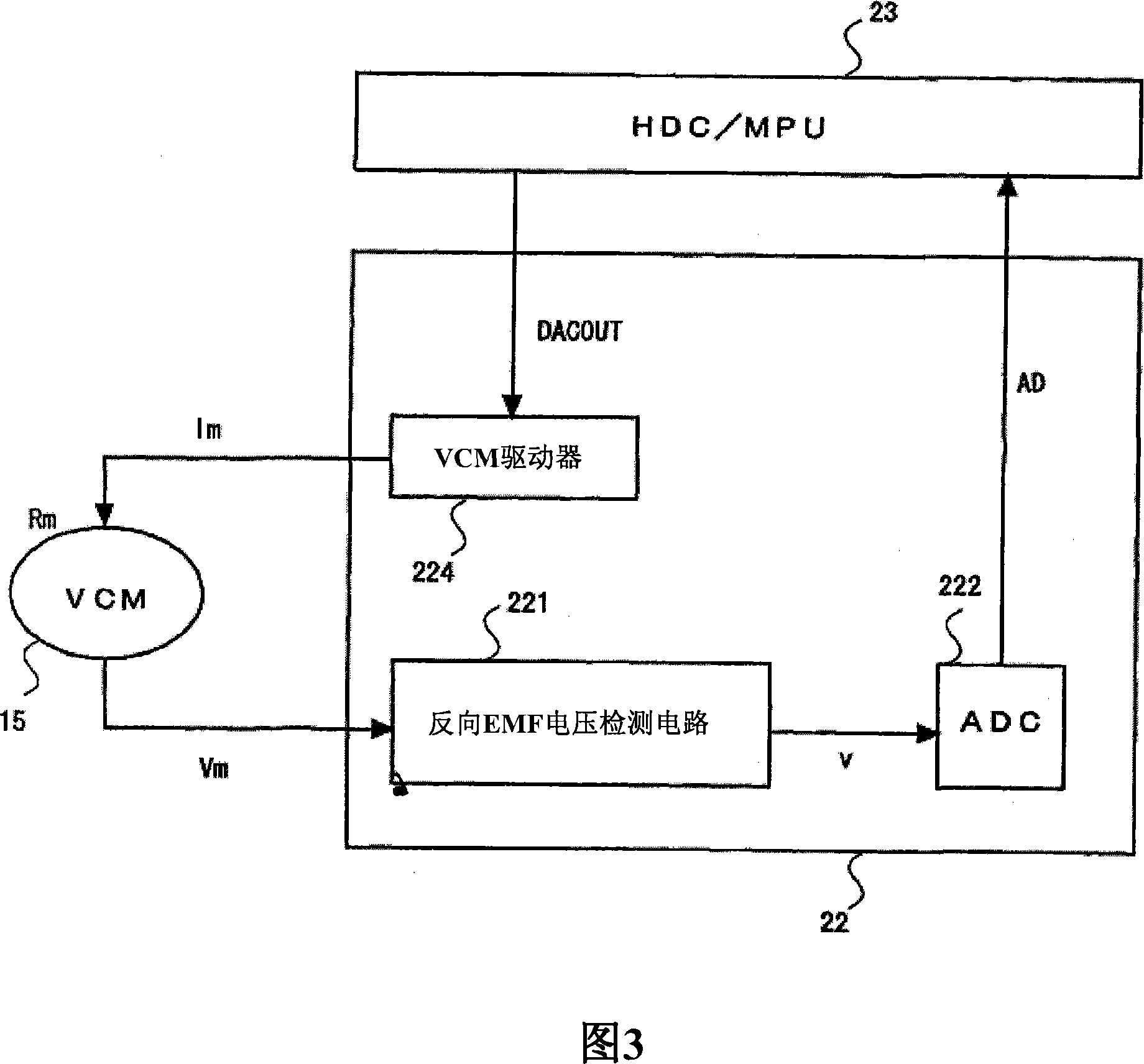
[0040] A feature of this embodiment is velocity feedback control of the VCM driving the actuator. The HDD includes a detection circuit and a controller for detecting the back EMF voltage of the VCM. The controller performs correction operation processing on the detected back EMF voltage, and executes speed feedback control of the VCM using the result of the operation. The controller calibrates the correction operation coefficient before...


PUM


Abstract

The invention relates to a disk drive device and calibration method thereof, which can help to prevent destabilization in VCM velocity control. According to the embodiment, an HDC / MPU 23 calibrates a correction operational coefficient of a detected back EMF voltage before unloading. The calibration is carried out in a state that an actuator 16 is pivoting. The HDC / MPU 23 calibrates the correction coefficient according to a motion equation of the actuator 16 using VCM current applied to a VCM 15 and a detected value of a back EMF voltage detection circuit 221.

Description

technical field [0001] The present invention relates to a disk drive and a calibration method therefor, in particular, to calibration for speed control of a voice coil motor. Background technique [0002] Disk drives using various media such as optical disks, magneto-optical disks and floppy disks are known in the art. In particular, hard disk drives (HDDs) have been widely used as storage devices for computers, and have been one of the indispensable disk drive devices for current computer systems. Also, HDDs have found widespread use due to their outstanding characteristics, such as removable memories used in moving image recording / reproducing apparatuses, car navigation systems, cellular phones, or digital cameras, and computers. [0003] Disks used in HDDs have multiple concentric data tracks. On each data track, a plurality of servo data including address information and a plurality of data sectors including user data are recorded. A plurality of data sectors are reco...

Claims


Application Information

Patent Timeline
Patent Type & Authority Applications(China)
IPC IPC(8): G11B21/12G11B21/21
CPCG11B5/553
Inventor 藏本健一坂元晋哉和佐信彦野尻沙绫香富永英文
Owner HITACHI GLOBAL STORAGE TECH NETHERLANDS BV
Why Eureka
Try Eureka