
Laser measuring instrument for railway work lifting and lining path

A laser measuring instrument and railway engineering technology, applied in the field of measuring instruments, can solve the problems that the detection method cannot meet the requirements of the railway engineering department for construction operations and daily line inspection, the measurement accuracy is poor, and the labor intensity is high, and the daily line maintenance is convenient. The effect of using, reducing labor intensity and improving work efficiency

Inactive Publication Date: 2008-07-30
济南蓝动激光技术有限公司
View PDF0 Cites 15 Cited by
  • Summary
  • Abstract
  • Description
  • Claims
  • Application Information

AI Technical Summary

Problems solved by technology

[0007] The present invention aims at the poor measurement accuracy, low efficiency, and high labor intensity of the smoothness measurement technology of the rail lifting and track shifting in the existing railway engineering department, and other detection methods cannot meet the requirements of the railway engineering department's construction work and daily line detection. The problem of not being able to adapt to the rapid development of railways is to provide a laser measuring instrument that can measure the long section of the track (not less than 200m), leveling, leveling and smoothing deviation, and can cooperate with large-scale machine operations. The measuring instrument is suitable for It is used in the construction work of the railway engineering department and the daily line inspection. It can detect the smoothness of the railway track, including the amount of lifting and shifting. It can also measure the height and direction of long sections and other parameters, and can transmit the data to the computer. , the data can be analyzed

Method used


Image

  • Laser measuring instrument for railway work lifting and lining path
  • Laser measuring instrument for railway work lifting and lining path
  • Laser measuring instrument for railway work lifting and lining path

Examples


Embodiment Construction

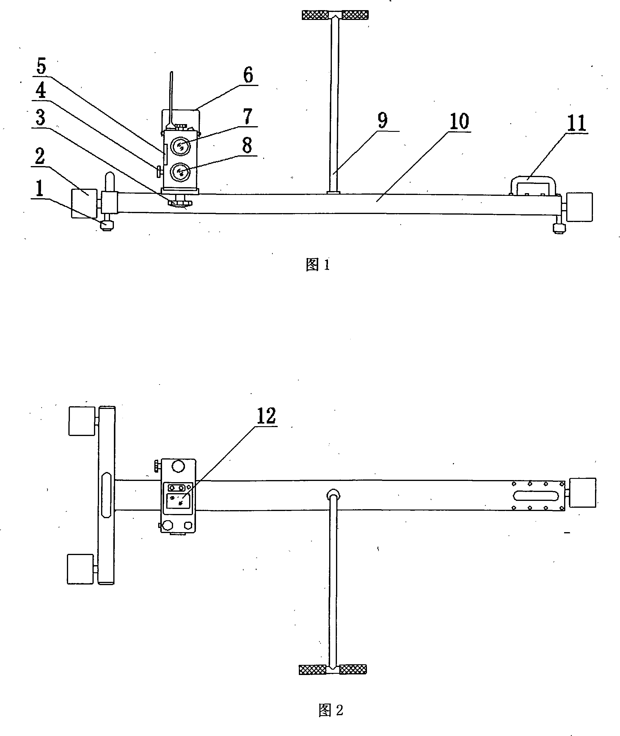
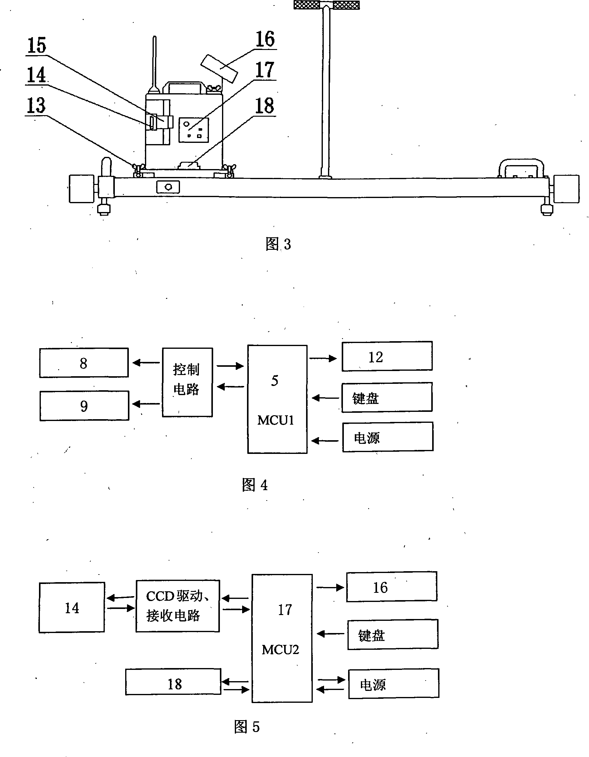
[0020] The laser measuring instrument for starting and setting railway tracks of the present invention includes a laser emitting device, a measuring device and a traveling trolley, and the laser emitting device and the measuring device are respectively installed on a traveling trolley. A wireless communication device is installed on the laser emitting device and the measuring device, and the two communicate through wireless. The walking trolley is made up of side wheels 1, walking wheels 2, push rod 10 and vehicle frame 11 (see Fig. 1). Wheel 1 is in contact with the side of the rail, and push rod 10 is installed on the vehicle frame 11 and can be disassembled when not in use. A handle 12 is installed on the vehicle frame 11, and the operator holds the handle 12 to make the walking trolley go up and down the road conveniently.

[0021] As shown in Figure 1, the laser emitting device is fixed on the walking trolley through the fastening knob 3. The laser emitting device includ...


PUM


Abstract

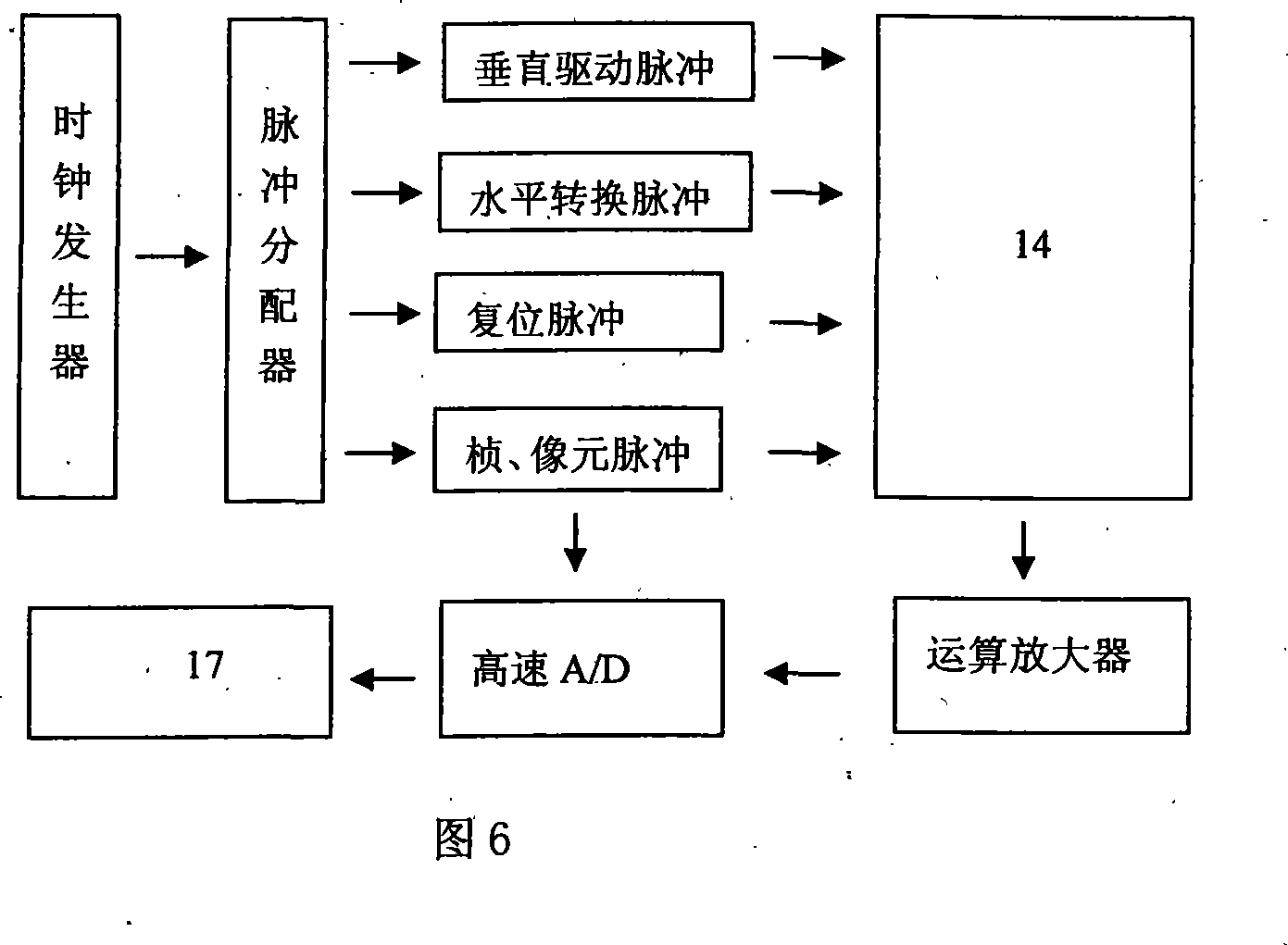
The invention discloses a laser measuring apparatus for track lifting and turning of railway engineering affairs, and the laser measuring apparatus comprises a laser emitter device, a measuring device and two travel dollies, wherein, the laser emitter device and the measuring device are respectively arranged on one travel dolly. A wireless communication device is arranged on the laser emitter device and the measuring device, wherein, the laser emitter device comprises a track lifting LASER, a turning track LASER, a laser data processor and a display, and the measuring device comprises an optic lens, a CCD sensor, a measured data processor, a display and a horizontal sensor. The invention utilizes the laser as a datum line, and the CCD sensor is used as a collimation detector, thus, the measuring problem of track lifting and turning quantity of steel rails with long length of over 200 metres of the railway engineering affairs is solved, and the smoothness of railway lines can be detected in the high precision way. The invention provides reliable measuring bases for railway maintenance and has the advantages of high measuring precision, operation efficiency improvement and reduction of the labor intensity of workers.

Description

technical field [0001] The invention relates to a measuring instrument used by the railway engineering department for the track setting operation of rails, in particular, it is an instrument and equipment used for leveling railway rails, finding deviations and cooperating with large engineering machinery. Background technique [0002] The smoothness of railway rails will be affected after long-term operation. The straight track becomes a track composed of many wavy "curves". The curved track is no longer smooth, which will cause the train to shake and snake. The increase of power accelerates the deformation of the ballast bed, which in turn expands the unevenness, thereby making the train more destructive to the track, thus forming a vicious circle. Moreover, the smoothness of the track will also cause the contact surface of the train wheel and rail to be subjected to large impact dynamics, accelerate the wear and fatigue damage of the wheel and rail, shorten the life of the...

Claims


Application Information

Patent Timeline
IPC IPC(8): G01B11/00G01B11/26G01B11/30E01B35/00G08C17/00
Inventor 王道睿林宪旗李朝正陈强杨宇孟群涛
Owner 济南蓝动激光技术有限公司
Learn More