Operating method for coal gasification combined cycle power plant

一种运转方法、发电设备的技术,应用在机械设备、燃烧设备、燃烧方法等方向,能够解决损伤燃料喷嘴、燃气涡轮运转故障、缩短燃烧器寿命等问题

Inactive Publication Date: 2010-12-08
KK TOSHIBA
View PDF3 Cites 0 Cited by
  • Summary
  • Abstract
  • Description
  • Claims
  • Application Information

AI Technical Summary

Problems solved by technology

Therefore, the internal pressure of the coal gasification fuel passage 14 for supplying the coal gasification fuel c is lower than the internal pressure of the burner sleeve 4 filled with the combustion gas 21 generated by the combustion of the liquid fuel a, as Figure 11 As shown by the middle arrow e, due to the pressure difference, the combustion gas 21 flows back from the side of the burner sleeve 4 into the coal gasification fuel flow path 14
[0018] In addition, even if no pressure difference occurs, the combustion gas 21 may flow back into the coal gasification fuel flow path 14 due to only fluctuations in the dynamic pressure of the combustion gas 21 or pressure fluctuations in the burner 1 .
[0019] This backflow phenomenon of the combustion gas 21 becomes a cause of damage to the fuel nozzle 5, causes troubles in the operation of the gas turbine, shortens the life of the combustor, etc., and causes various problems in terms of use and economy.

Method used


Image

  • Operating method for coal gasification combined cycle power plant
  • Operating method for coal gasification combined cycle power plant
  • Operating method for coal gasification combined cycle power plant

Examples


no. 1 Embodiment

[0038] The first embodiment ( Figure 1 ~ Figure 3 )

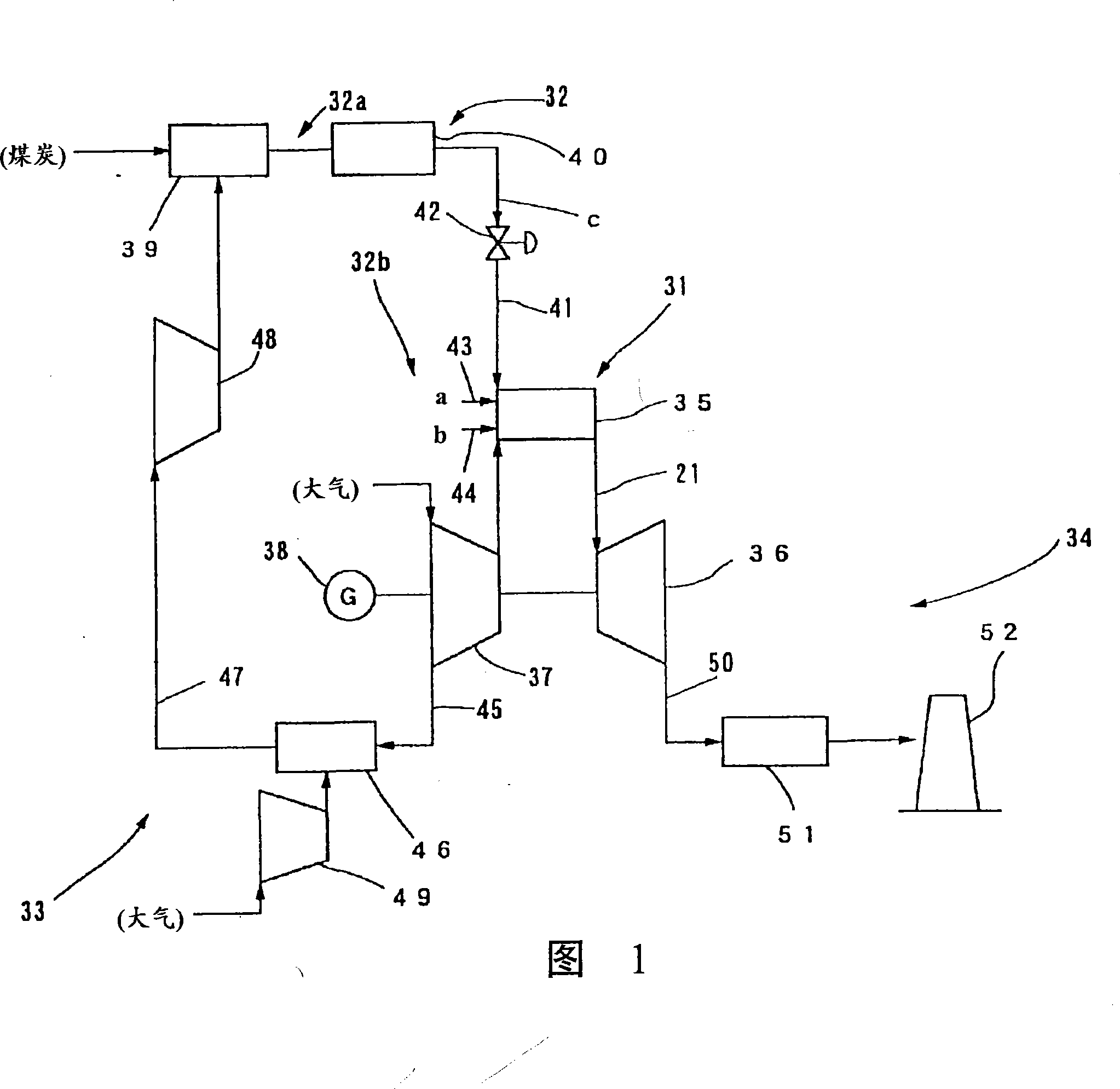
[0039] figure 1 It is a systematic diagram showing the overall structure of the combined coal gasification power generation facility of the embodiment of the present invention.

[0040] like figure 1 As shown, the combined coal gasification power generation equipment of this embodiment generally includes: a gas turbine system 31; a fuel supply system 32; an air supply system 33; an exhaust system 34 and so on.

[0041] The gas turbine system 31 has: a burner 35 capable of selectively combusting coal gasification fuel c and liquid fuel a; a gas turbine 36 driven by combustion gas generated by the burner 35; coaxially arranged with the gas turbine 36 Gas turbine compressor 37 and generator 38.

[0042] The fuel supply system 32 is composed of two systems of a coal gasification fuel supply system 32a and a liquid fuel supply system 32b. The coal gasification fuel supply system 32a has a gasification furnace 39 for gasi...

no. 2 Embodiment

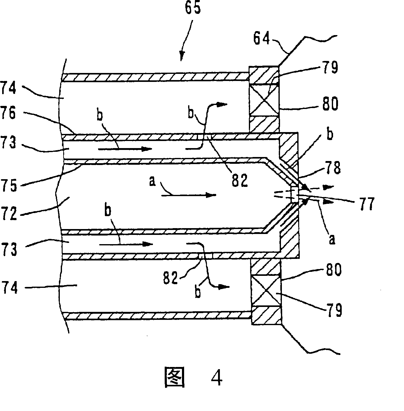
[0058] The second embodiment ( Figure 4 )

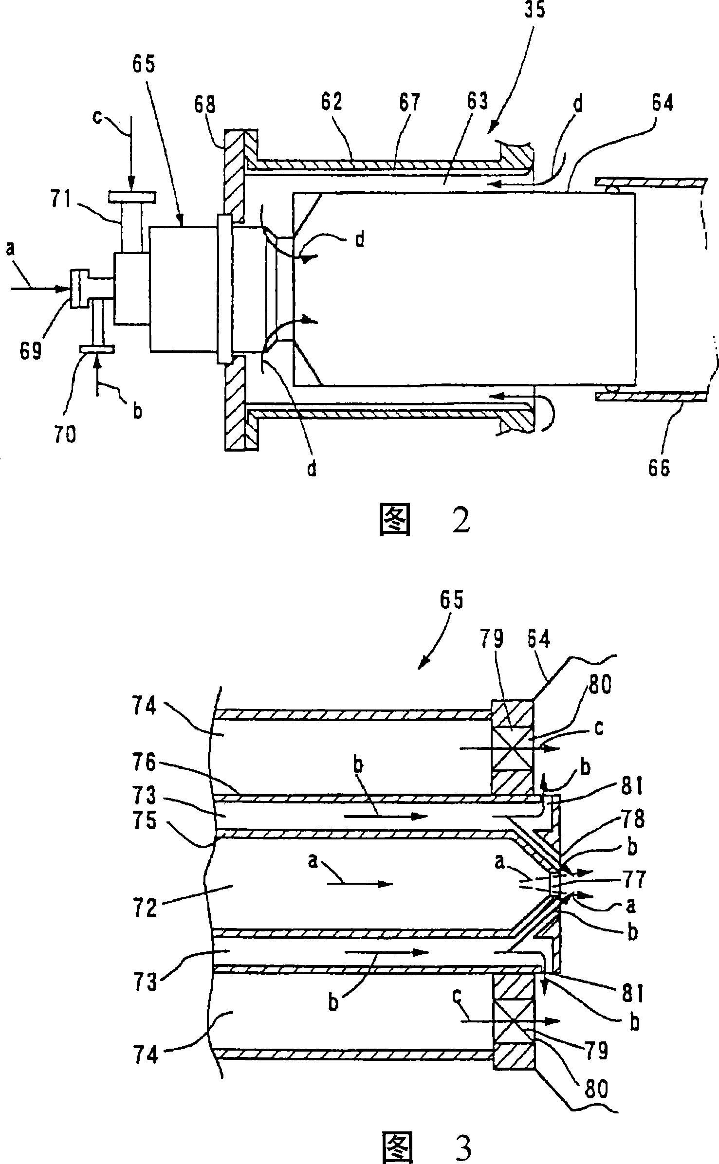
[0059] Figure 4 It is an enlarged cross-sectional view showing the fuel nozzle 65 portion of the burner 35 in the coal gasification fuel combined power generation facility of this embodiment.

[0060] This example Figure 4 As shown, on the fuel nozzle 65 that sprays fuel to the burner 35, a liquid fuel flow path 72, an air flow path 73 for atomization, and a coal gasification fuel flow path 74 are arranged in a state of being adjacent to each other. The flow path wall 76 near the outlet of the air flow path 73 for atomization is provided with a spray hole 82 for blowing atomization air into the fuel flow path for coal gasification. The spray holes 82 for the atomization air are formed in a plurality along the circumferential direction of the fuel nozzle 65, and are opened near the discharge ports 80 of the coal gasification fuel flow path 74, for example, continuously spray particles to the inner surface of the swirler 79. The...

no. 3 Embodiment

[0064] The third embodiment ( Figure 5 )

[0065] Figure 5 It is an enlarged cross-sectional view showing the combustion nozzle 65 of the burner 35 in the combined coal gasification power generation facility of this embodiment.

[0066] This example Figure 5 As shown, in will come from the gas turbine compressor 37 (refer to figure 1) is blown into the outlet portion of the combustion air passage 63 in the burner sleeve 64, and a combustion air ejection portion 83 for ejecting combustion air to the outlet portion of the coal gasification fuel flow passage 74 is provided. . The combustion air ejection portion 83 includes: for example, a hole 84 pierced on the end wall 64a of the burner sleeve 64 on the combustion nozzle 65 side; The guide member 85 protruding from the inner surface continuously injects the combustion air d to the outside of the swirler 79 of the coal gasification fuel injection port 80 , and an air film can be formed on the coal gasification fuel injec...


PUM


Abstract

The invention provides an integrated coal gasification combined cycle power plant and an operation method that can prevent the reverse flow of fuel gas into a coal gasification fuel flow passage during the operation using liquid fuel, stabilize the operation of a gas turbine, and prolong the service life of a combustion equipment by thus eliminating the cause of damage to a fuel nozzle. The gas turbine system includes a combustor for selectively burning a coal gasification fuel obtained by gasifying a coal and a liquid fuel. The fuel supply system is provided with a liquid fuel supply passagethrough a fuel nozzle provided for the combustor, an atomization air supply passage and a coal gasification fuel supply passage. In addition, a branch outletis provided in the outlet section of the air flow passage for atomization to jet atominizing air toward the outlet section of the coal gasification fuel flow passage.

Description

[0001] This application is a divisional application of the Chinese invention patent application with the filing date of August 20, 1998, the application number of 98118636.X, and the title of "combined coal gasification power generation equipment and its operation method". technical field [0002] The present invention relates to a combined coal gasification power generation facility that selectively combusts coal gasification fuel and liquid fuel to obtain power, and an operation method thereof, and particularly relates to appropriately preventing combustion gas from occurring in a fuel flow path of coal gasification fuel when liquid fuel is used Combined coal gasification power generation equipment and its operation method for improving the safety of the burner part by reverse flow. Background technique [0003] In recent years, from the viewpoint of effective utilization of natural resources, research on coal gasification power plants using coal gasification fuel as a heat...

Claims


Application Information

Patent Timeline
Patent Type & Authority Patents(China)
IPC IPC(8): F23R3/36F23N1/00C10J3/46F02C3/28F02C7/22F02C7/232F23D17/00F23R3/26F23R3/28
CPCY02E20/16F02C3/28F23R2900/00002F23D17/002Y02E20/18F23R3/36
Inventor 小野田昭博岩井保宪
Owner KK TOSHIBA
Why Eureka
Try Eureka