


Quick Research
Generate reliable direction feasibility study reports for your R&D in just a few steps.

Technical Q&A
Discover and master advanced knowledge NOW. Basics, ideas, possibilities, all at once.

Find Solutions
As an expert in R&D theories, this can generate solutions to your technical problems instantly.

Evaluate Feasibility
Analyze your overall solution with one click, know your potential R&D risks in advance.

Monitor Landscape
Get weekly tech updates, stay abreast of the latest tech innovations and key insights.
Operating method for coal gasification combined cycle power plant
An operation method and technology for power generation equipment, applied in mechanical equipment, combustion equipment, combustion methods, etc., can solve the problems of gas turbine operation failure, shortening the life of the burner, damage to the fuel nozzle, etc.
- Summary
- Abstract
- Description
- Claims
- Application Information
AI Technical Summary
Problems solved by technology
Method used
Image

Examples
no. 1 Embodiment
[0038] The first embodiment (Fig. 1 to Fig. 3)
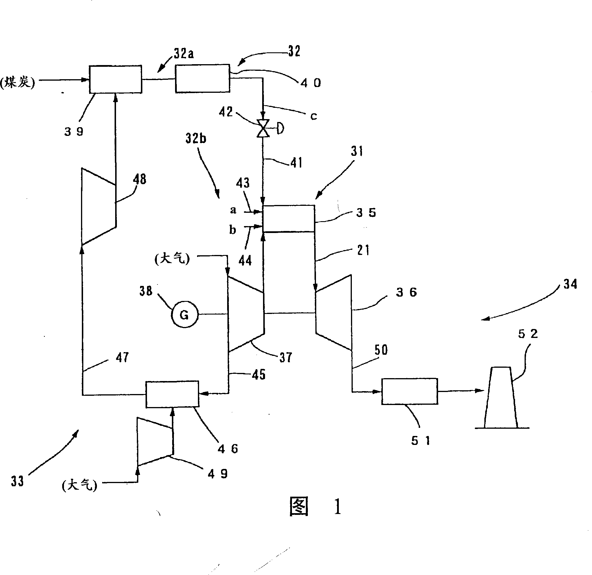
[0039] FIG. 1 is a system diagram showing the overall structure of a combined coal gasification power generation facility according to an embodiment of the present invention.
[0040] As shown in FIG. 1 , the combined coal gasification power generation equipment of this embodiment generally includes: a gas turbine system 31 ; a fuel supply system 32 ; an air supply system 33 ; an exhaust system 34 and so on.
[0041] The gas turbine system 31 has: a burner 35 capable of selectively combusting coal gasification fuel c and liquid fuel a; a gas turbine 36 driven by combustion gas generated by the burner 35; coaxially arranged with the gas turbine 36 Gas turbine compressor 37 and generator 38.
[0042] The fuel supply system 32 is composed of two systems of a coal gasification fuel supply system 32a and a liquid fuel supply system 32b. The coal gasification fuel supply system 32a has a gasification furnace 39 for gasifying coal an...
no. 2 Embodiment
[0058] The second embodiment (Fig. 4)
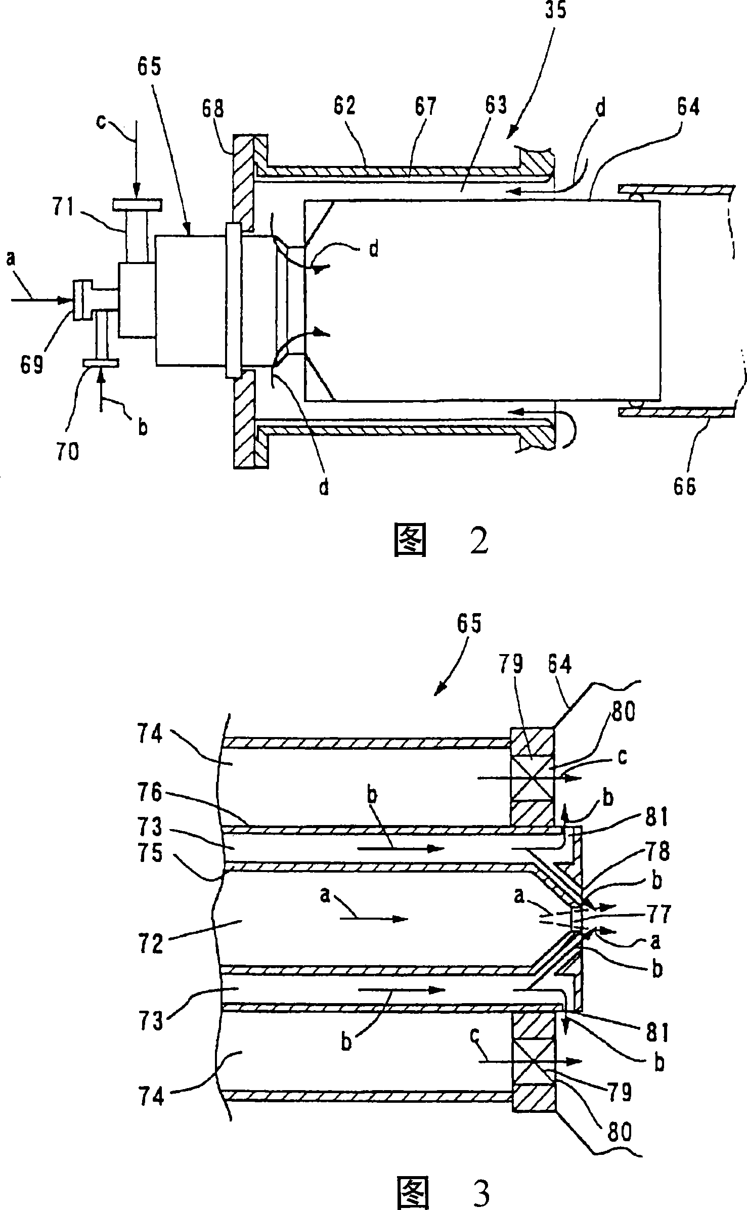
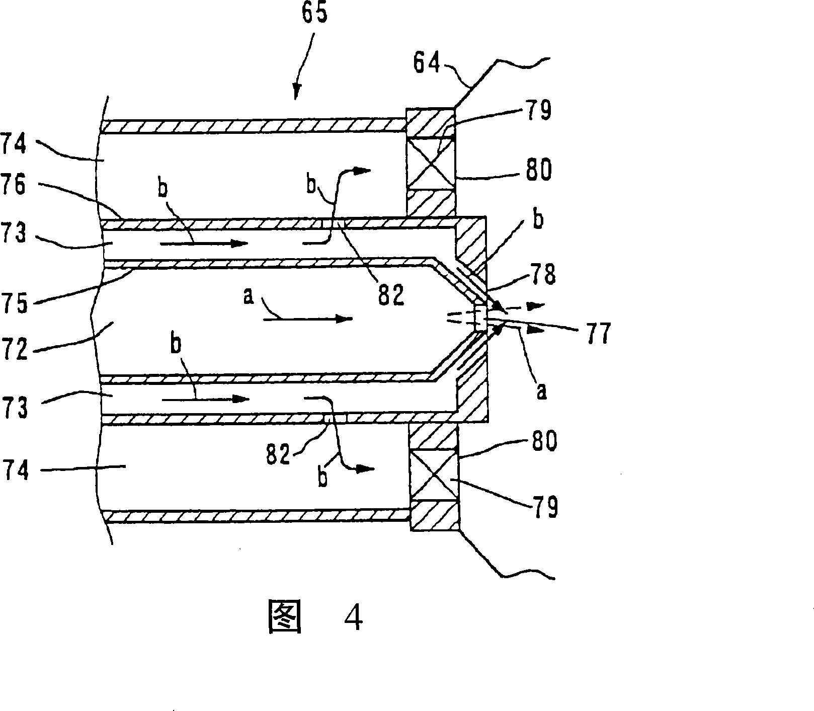
[0059] Fig. 4 is an enlarged cross-sectional view showing a fuel nozzle 65 portion of the burner 35 in the coal gasification fuel combined power generation facility of this embodiment.
[0060] In this embodiment, as shown in FIG. 4 , a liquid fuel flow path 72 , an air flow path 73 for atomization, and a coal gasification fuel flow path are arranged adjacent to each other on the fuel nozzle 65 that ejects fuel to the burner 35 . 74, and on the flow path wall 76 near the outlet of the atomization air flow path 73, there is provided a spray hole 82 for blowing atomization air into the coal gasification fuel flow path. The spray holes 82 for the atomization air are formed in a plurality along the circumferential direction of the fuel nozzle 65, and are opened near the discharge ports 80 of the coal gasification fuel flow path 74, for example, continuously spray particles to the inner surface of the swirler 79. Then, the air b for atomizat...
no. 3 Embodiment
[0064] The third embodiment (Fig. 5)
[0065] Fig. 5 is an enlarged cross-sectional view showing the combustion nozzle 65 of the burner 35 in the combined coal gasification combined power generation facility of this embodiment.
[0066] In this embodiment, as shown in FIG. 5 , at the outlet of the combustion air flow path 63 that blows the combustion air d from the gas turbine compressor 37 (refer to FIG. 1 ) into the combustor sleeve 64, a gasification channel is provided. A combustion air ejection portion 83 ejects combustion air from an outlet portion of the fuel flow path 74 . The combustion air ejection portion 83 includes: for example, a hole 84 pierced on the end wall 64a of the burner sleeve 64 on the combustion nozzle 65 side; The guide member 85 protruding from the inner surface continuously injects the combustion air d to the outside of the swirler 79 of the coal gasification fuel injection port 80 , and an air film can be formed on the coal gasification fuel injec...
PUM
 Abstract
Description
Claims
Application Information
 - R&D Engineer
- R&D Manager
- IP Professional
- Industry Leading Data Capabilities
- Powerful AI technology
- Patent DNA Extraction
Browse by: Latest US Patents, China's latest patents, Technical Efficacy Thesaurus, Application Domain, Technology Topic, Popular Technical Reports.
© 2024 PatSnap. All rights reserved.Legal|Privacy policy|Modern Slavery Act Transparency Statement|Sitemap|About US| Contact US: help@patsnap.com