
Reamer comprising a cutting plate

A reamer and plate cutting technology, which is applied in the direction of reamers, forming knives, metal processing equipment, etc., can solve the problems of high friction coefficient factor, heat generation, and lower surface quality, so as to improve the drilling surface, increase the service life of tools, The effect of increasing the service life

Inactive Publication Date: 2008-07-23
MAPAL FABRIK FUER PRAEZISIONSWERKZEUGE (DE)
View PDF2 Cites 0 Cited by
  • Summary
  • Abstract
  • Description
  • Claims
  • Application Information

AI Technical Summary

Problems solved by technology

[0009] However, all cutting plates of the prior art for reamers have the common disadvantage that the flat chip-carrying surfaces of the main and auxiliary cutting edges are facing the cutting edges, which collect chips especially in the area of ​​the auxiliary cutting edges and thus in the During finishing machining of workpieces, increased chip evacuation leads to higher coefficient of friction and heat generation due to chip clogging and reduces surface quality

Method used


Image

  • Reamer comprising a cutting plate

Examples


Embodiment Construction

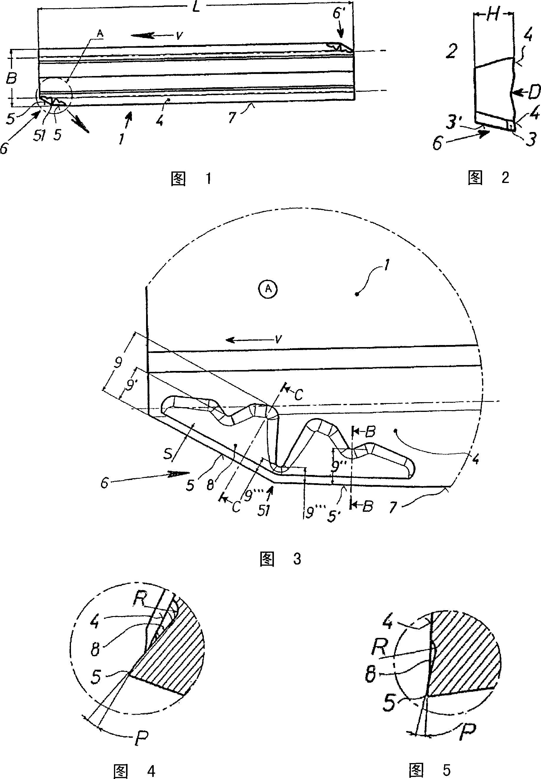
[0026] A plan view and a cross-sectional view of an indexable insert for reamer insertion are shown in FIGS. 1 and 2 . The indexable insert 1 has, for example, a length L of 16.5 mm, a width B of 3.6 mm and a thickness H of 2 mm, and has cutouts 6, 6' at opposite corners. A main cutting edge consisting of two cutting edge parts 5, 5' having a transition portion 51 can be formed in the cut-off 6. The secondary cutting edge 7 is formed in a direction opposite to the shown reamer feed direction V, or in the continuation of the primary cutting edge 5, 5'.

[0027] FIG. 2 shows an indexable plunger 1 in a sectional view, which has a bearing surface 2 for the insertion of the reamer in the working area. The tool flanks 3, 3' and the chip-carrying surface 4 form the main cutting edge 5, 5' and the secondary cutting edge 7, respectively.

[0028] The cutting section 6 of the cutting board 1 is shown in FIG. 3 . The cut-off portion 6 has a main cutting edge 5 at a relatively la...


PUM


Abstract

The invention relates to a reamer comprising a shaft with a pulling portion and an axially opposite working area thereof, the working area having at least one interchangeable tool part and at least one pressure element attached thereto. The tool part is a hard metal cutting plate (1), in particular an indexable insert. According to the invention, in order to ensure short chips in the main cutting edge area and to avoid chip accumulation or easy chip discharge in the auxiliary cutting edge area, the cutting plate (1) has a distance (S) of at least 0.02 mm from the cutting edge (5, 5'). The chip-carrying surface (4) has a roughening depth at least partially increased by at least 0.01 mm on one side in the region of the cutout (6). The aforementioned object is also achieved by the cutting plate (1) having at least one chip chamber (8) in its chip-carrying surface (4) at a distance of at least 0.02 mm from the main cutting edge (5) on the end side in the area of ​​the cut-off (6) to fulfill.

Description

technical field [0001] The invention relates to a reamer comprising a shaft with a traction part and an axially opposite working area with at least one interchangeable tool part and at least one pressure part, wherein the tool part Cutting plates of hard metal up to 25 mm in length, 8 mm in width and approximately 4 mm in height or thickness, especially designed as indexable inserts, having flat bearing surfaces in longitudinal section, each forming at least one main cutting edge and a secondary cutting edge tool side, chip-carrying surface and substantially concave pressure surface adapted to the clamping shoe, viewed from above, is a pluggable adjustable insertable at its end substantially parallel to the shaft axis for cutting The auxiliary cutting edge has a cut-off portion at an angle to the shaft axis in the feed direction of the reamer with at least one main cutting edge. Background technique [0002] Numerous indexable inserts for turning, reaming, planing, milling,...

Claims


Application Information

Patent Timeline
Patent Type & Authority Applications(China)
IPC IPC(8): B23D77/02
CPCB23D77/02B23D2277/26B23D2277/30Y10T407/23Y10T407/24Y10T407/2268Y10T407/245B23D77/00
Inventor 沃尔特·巴恩特哈勒阿敏·史莱默克劳斯·鲁埃茨乌迪尔
Owner MAPAL FABRIK FUER PRAEZISIONSWERKZEUGE (DE)
Learn More