
High pressure temperature on-line monitoring photoelectricity inversion thimble structure

A photoelectric converter and high-voltage technology, applied in radiation pyrometry, electric radiation detectors, measuring devices, etc., can solve the problems of affecting power supply of other circuits, not allowing long-term power outages, etc., and achieve equipment condition maintenance and distribution Power grid automation, convenient equipment condition maintenance and distribution network automation, the effect of safe use

Inactive Publication Date: 2010-07-21
陈津
View PDF1 Cites 0 Cited by
  • Summary
  • Abstract
  • Description
  • Claims
  • Application Information

AI Technical Summary

Problems solved by technology

However, for the renovation of the equipment in the running state, the main bus must be powered off before installation, which will affect the power supply of other circuits, especially for important circuits, it is not allowed to cut off the power for a long time

Method used


Image

  • High pressure temperature on-line monitoring photoelectricity inversion thimble structure
  • High pressure temperature on-line monitoring photoelectricity inversion thimble structure
  • High pressure temperature on-line monitoring photoelectricity inversion thimble structure

Examples


Embodiment 1

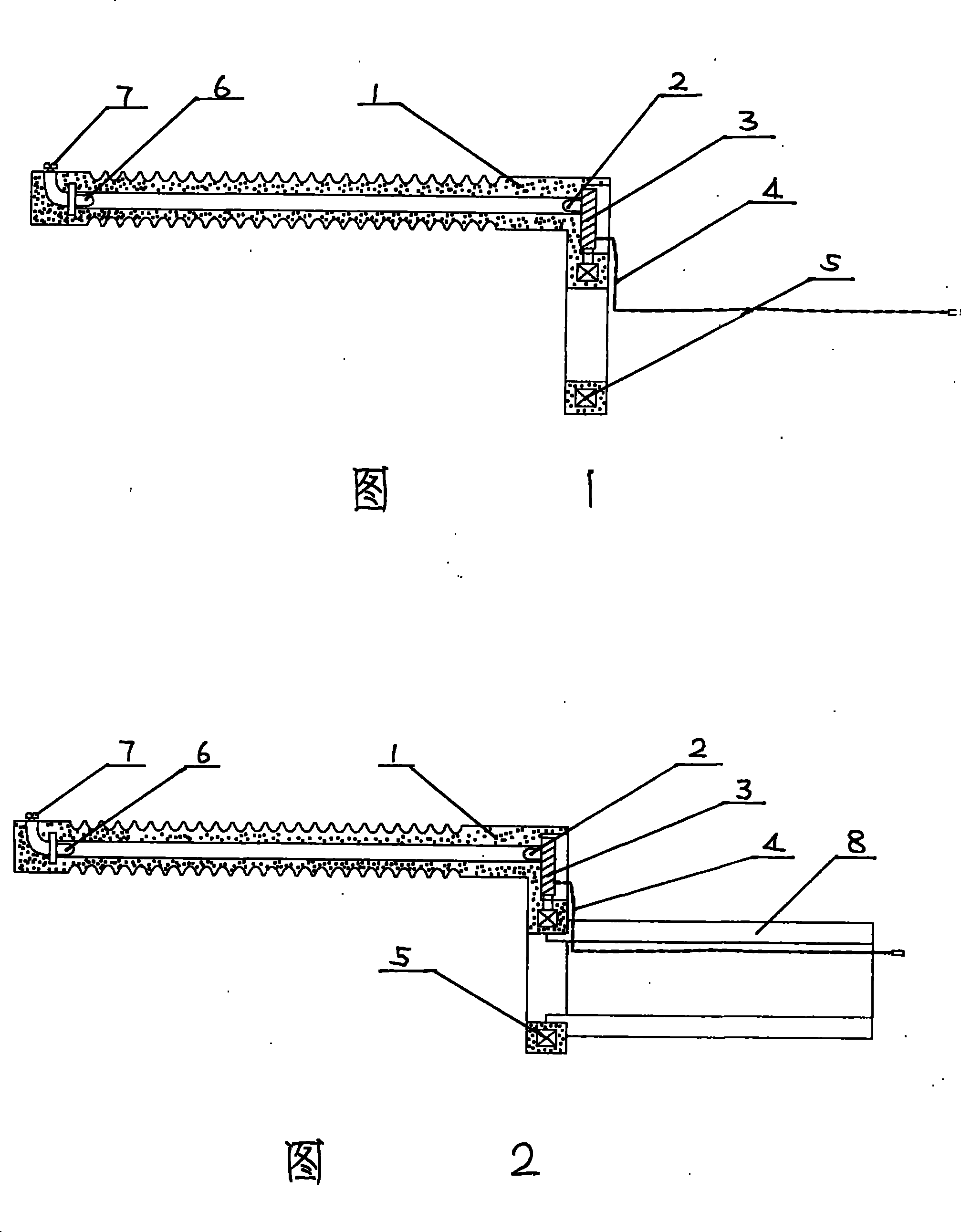
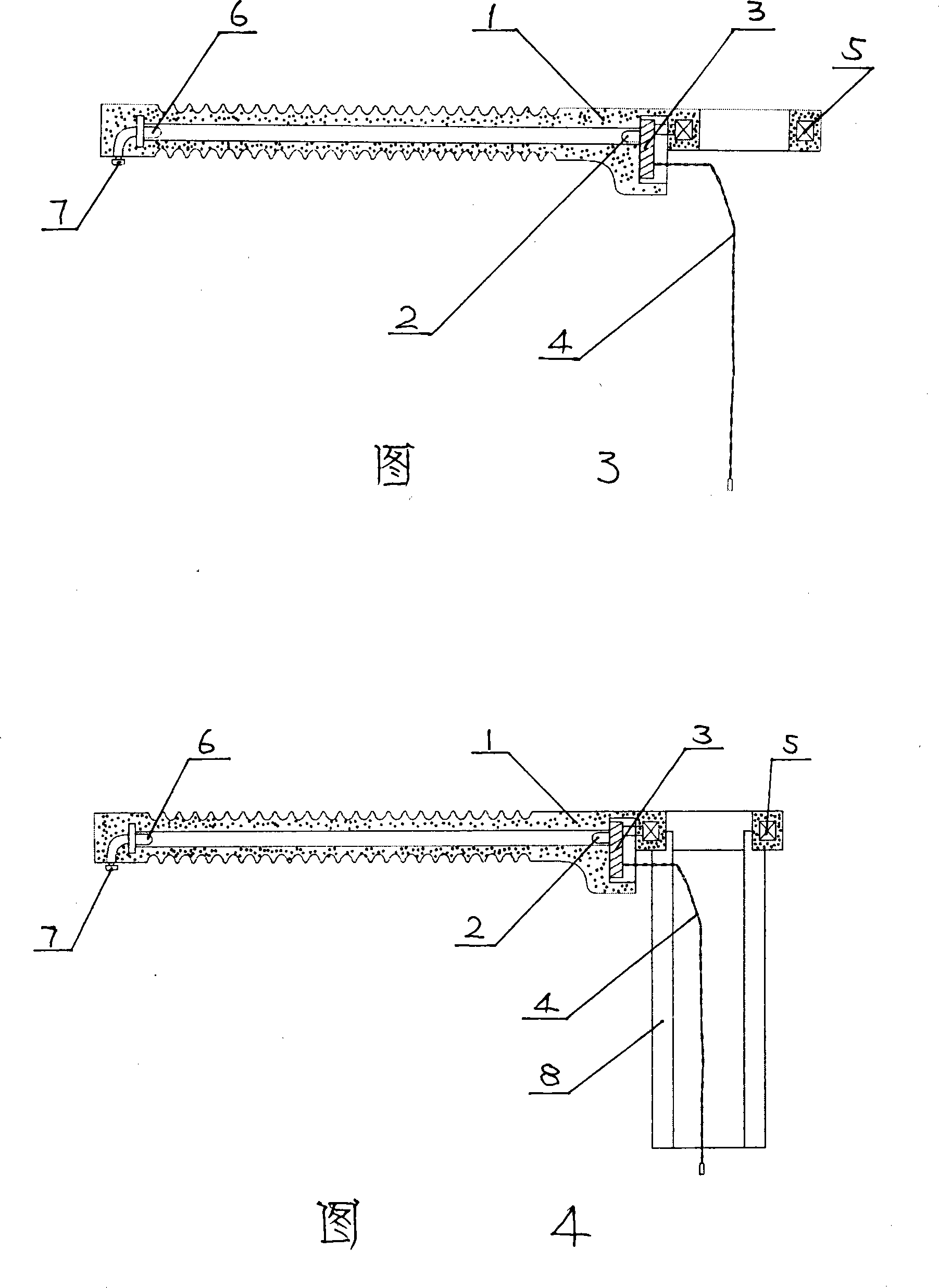
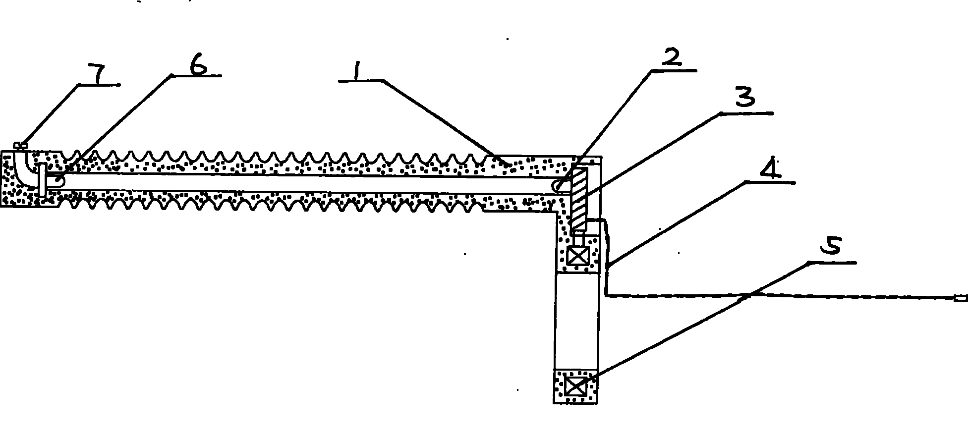
[0019] Please refer to Fig. 1, there is a collar main body 1, and a circular collar is arranged on the front end of the collar main body 1, and an inductive power supply 5 is embedded inside the collar; the upper end of the collar main body 1 is provided with a photoelectric transducer 3; The other end connected with the lead wire is connected with the induction power supply 5; the photoelectric transducer 3 is connected with a thermal detector 4, and the thermal detector 4 touches the external temperature detection part; the inner end of the photoelectric transducer 3 is connected with the infrared emission tube 2, and the infrared emission The tube 2 corresponds to a transparent hole, and the other end of the hole is provided with an infrared receiving tube 6, and the other end of the infrared receiving tube 6 is connected to the signal output terminal 7; the terminal 7 is connected to the external control unit through a wire.

Embodiment 2

[0021] see figure 2 , there is a collar main body 1, a circular collar is arranged at the front end of the collar main body 1, a sleeve 8 is embedded in the circular collar, and an induction power supply 5 is embedded inside the collar; the upper end of the collar main body 1 is provided with a photoelectric conversion 3; the other end of the photoelectric transducer 3 connected with the lead wire is connected with the induction power supply 5; the photoelectric transducer 3 is connected with a thermal detector 4, and the thermal detector 4 touches with the external detection temperature position; the inner end of the photoelectric transducer 3 is connected with the infrared The transmitting tube 2 is connected, and the infrared transmitting tube 2 has a transparent hole correspondingly. The other end of the hole is provided with an infrared receiving tube 6, and the other end of the infrared receiving tube 6 is connected to the signal output terminal 7; the terminal 7 is conne...


PUM


Abstract

The invention discloses a high-voltage temperature online monitoring photoelectric conversion sleeve-ring structure, belonging to a temperature online monitoring device for high voltage electric power equipments. The photoelectric conversion sleeve-ring structure is provided with a sleeve ring body, a circular sleeve ring is arranged at front end of the sleeve ring body, an induction power sourceis embedded inside the sleeve ring, a photoelectric converter is arranged at upper end of the sleeve ring body, the other end of the photoelectric convertor connected with lead wires is connected with the induction power source, the photoelectric converter is connected with a thermal detector, the thermal detector and external detection temperature position contact with the sensing temperature signal, the inner port of the photoelectric converter is connected with an infrared transmitting tube, the infrared transmitting tube is correspondingly provided with a permeable hole, an infrared receiving tube is arranged at the other end of the hole, the other end of the infrared receiving tube is connected with a signal output wiring terminal, the wiring terminal is connected with an external control unit by wires. The photoelectric conversion sleeve-ring structure can realize temperature online monitoring of high-voltage electric power equipments, reduce the accidents of electric power equipments, and improve the reliability of electric supply, and is convenient to realize equipment state maintenance and distribution network automation, and has good social benefit.

Description

technical field [0001] The invention relates to an on-line temperature monitoring device for high-voltage power equipment, in particular to a photoelectric conversion collar structure for on-line high-voltage temperature monitoring. Background technique [0002] The poor electrical contact state of the conductive connection and socket of the power equipment is an important reason for the overheating of the place, even under normal current, the maximum allowable temperature will be exceeded. The parts of the switchgear that often fail are the contacts and the cable connections of the incoming and outgoing wires. Most of these devices are closed structures, and the doors or covers that block infrared radiation cannot be opened during operation for infrared detection; some outdoor devices are inconvenient to detect, and the detected temperature is not accurate and cannot be monitored online. [0003] For the current on-line monitoring of the temperature of the removable switch...

Claims


Application Information

Patent Timeline
Patent Type & Authority Patents(China)
IPC IPC(8): G01J5/00G01J5/28
Inventor 陈津
Owner 陈津
Learn More