
Method for reduction of temperature during period of building well for deep well coal mine and equipment thereof

A technology for coal mines and deep wells, applied in the field of cooling during well construction, can solve the problems of increasing underground temperature and drainage, equipment can no longer be reused, and expensive cold air station equipment, so as to achieve less cooling loss, reduce underground humidity and drainage, The effect of high cooling conversion efficiency

Inactive Publication Date: 2008-07-23
郎庆田 +1
View PDF0 Cites 8 Cited by
  • Summary
  • Abstract
  • Description
  • Claims
  • Application Information

AI Technical Summary

Problems solved by technology

[0003] At present, the forced cooling measures during the construction of wells: First, build a cold air station on the ground to directly send cold air to the tunneling face; the disadvantage is that the equipment of the cold air station is expensive, and when the main shaft and the auxiliary shaft are connected, the equipment cannot be reused when it is idle
The second is to set up a water-cooling unit on the ground to reduce the water temperature to low temperature water of 5-10°C, and the fan sends cold air to the tunneling face through the condenser; the disadvantage is that the cooling capacity is large, the cooling effect is poor, and the economic effect is poor
The third is to directly put ice cubes in the air duct to cool the air flow, or to spray the refrigerated low-temperature water in the air duct in the form of a mist to cool the air flow (such as the village mine in South Africa); temperature and displacement

Method used


Image

  • Method for reduction of temperature during period of building well for deep well coal mine and equipment thereof
  • Method for reduction of temperature during period of building well for deep well coal mine and equipment thereof
  • Method for reduction of temperature during period of building well for deep well coal mine and equipment thereof

Examples


Embodiment Construction

[0027] The present invention will be further described below in conjunction with an embodiment and accompanying drawings.

[0028] Example overview:

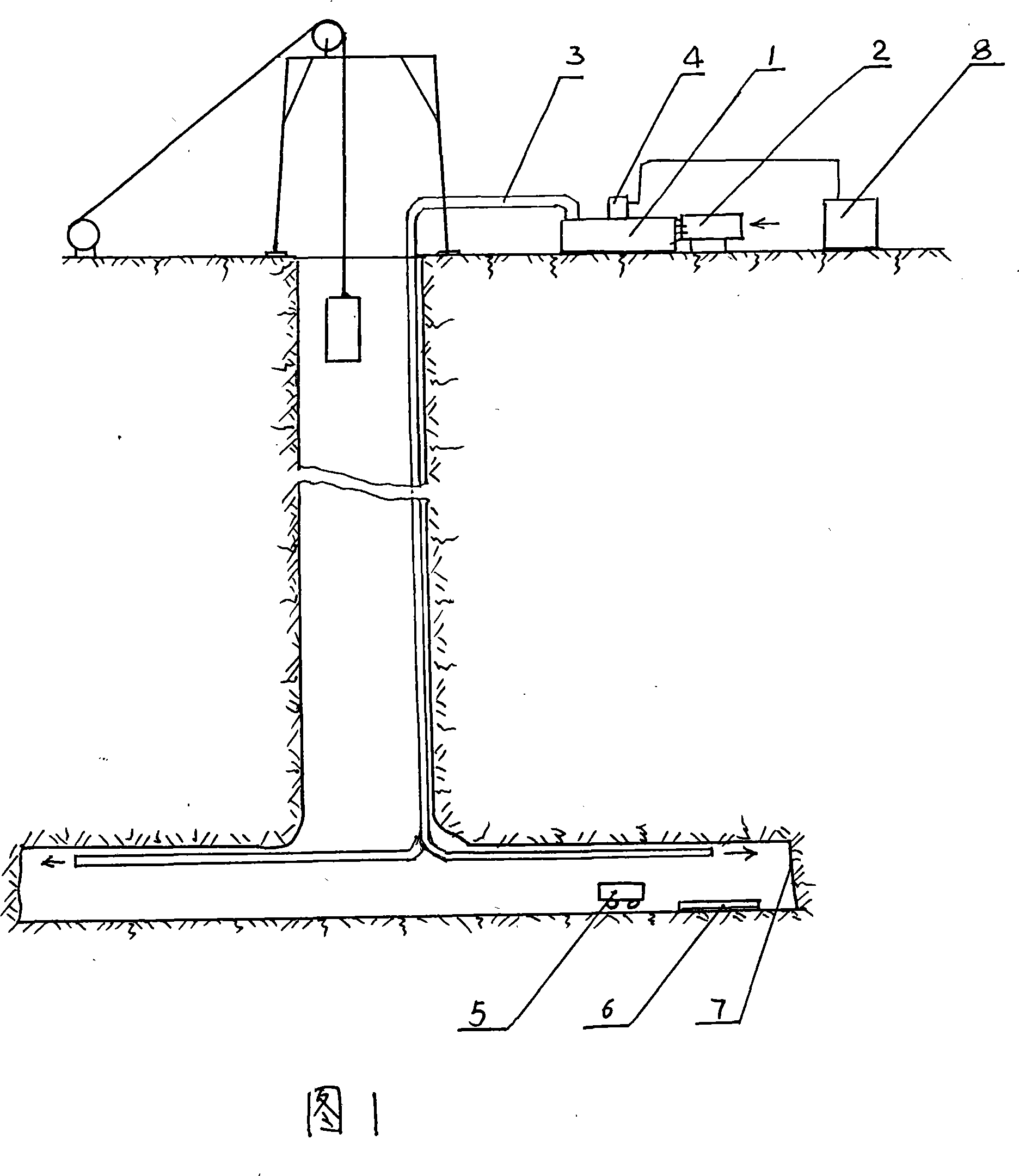
[0029] A coal mine has a mining depth of more than 800 meters. When the main and auxiliary shafts are dug, the temperature exceeds 32°C, and the groundwater temperature at the working face exceeds 46°C. After the shaft is dug to the bottom, two roadway working faces need to be constructed at the same time. In order to ensure normal construction, it is necessary to take cooling measures, and it is required to drop below 30°C. After calculation, the required air volume of each working face is 400m 3 / min, the local natural wind temperature needs to be 27°C, and it needs to drop below 21°C before sending it down the well with the air duct to meet the cooling requirements of shaft construction. When the wellbore continues to deepen, 200kg of cooling capacity of -5°C flake ice per hour is needed to meet the cooling requirements.

...


PUM


Abstract

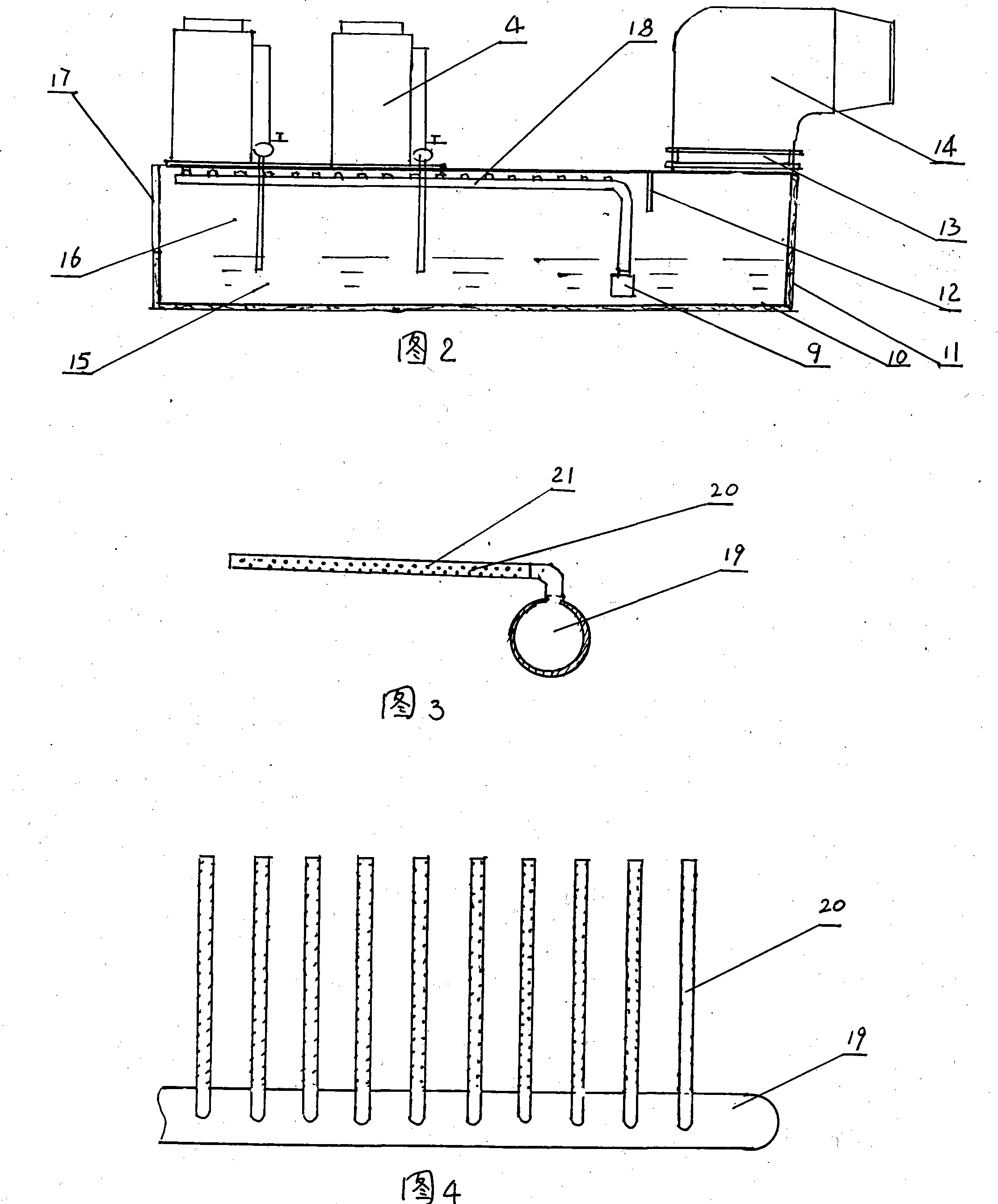
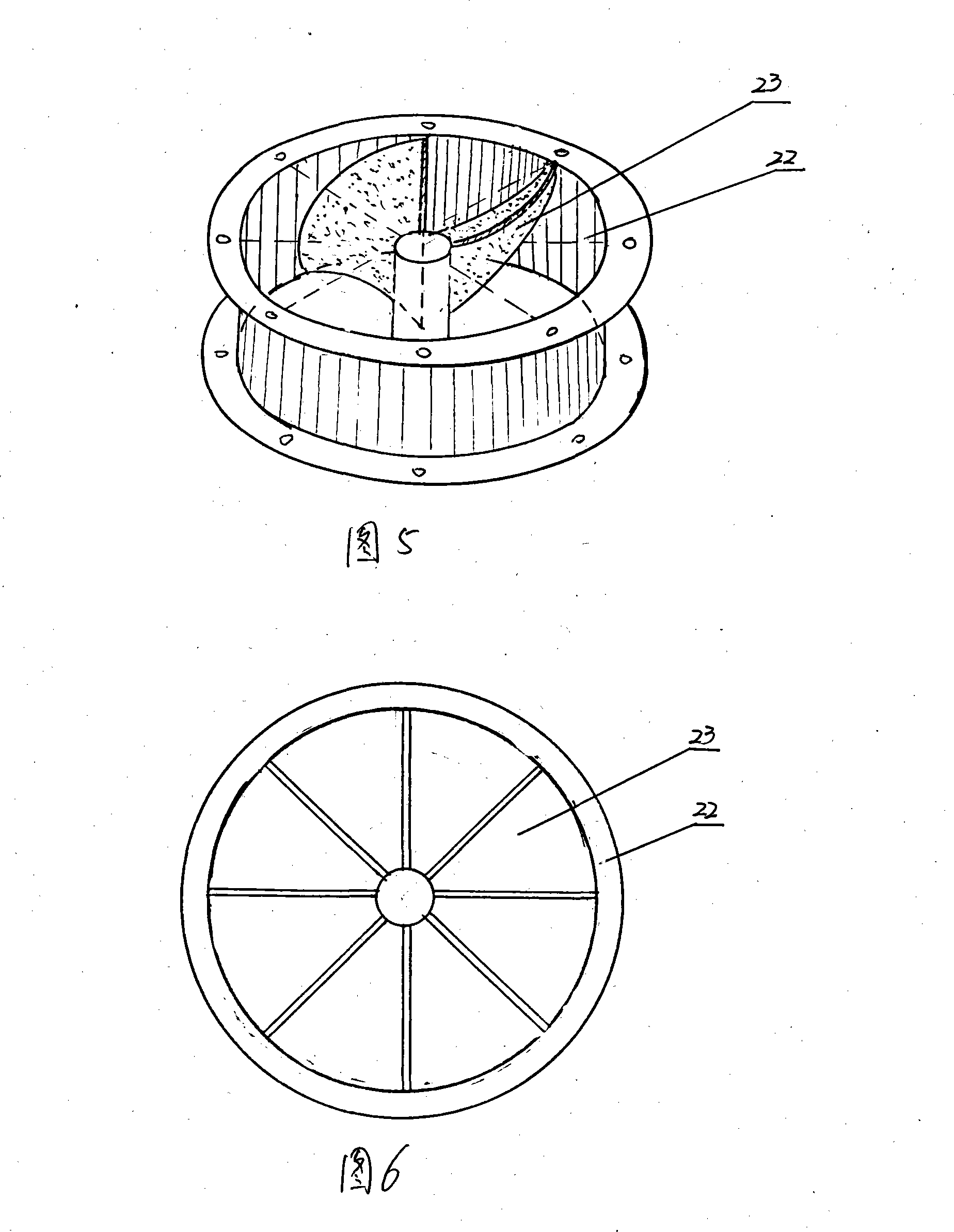
The invention discloses a cooling method and device in building deep well coal mine, belonging to the field of building coal mine well, which is characterized in that a refrigeration station, a counter-rotating fan, and a cooling unit composed by an ice maker and a thawing tank are arranged on the ground near the well head; the refrigeration station generates cold and the ice maker produces flake ices; a part of the flake ices is transferred into the thawing tank, and generates cold twice to cool the tunneling face, and the other part is transferred to the tunneling face by a container, and generates radiation cold via a cold box to cool the tunneling face again. The cooling method and device in building deep well coal mine has the advantages of low cost, low cold loss, high cold conversion efficiency, energy saving, high cold transferred to the tunneling face, good cooling effect, dry wind result, reduced underground humidity and water placement, easy movement, repeated use in the other well after one is finished, and no laying and waste.

Description

technical field [0001] The invention relates to a coal mine well construction method, in particular to a cooling method during well construction. Background technique [0002] At present, with the deepening of coal mining depth, it is necessary to excavate vertical shafts with a depth of more than 800 meters. The deeper the excavation depth, the higher the gushing water temperature of the excavation face, which generally exceeds 45°C, and the temperature at the beginning of the excavation face exceeds 32°C, which exceeds the "Coal Mine Safety Regulations" that construction can only be carried out below 30°C. Therefore, when the production ventilation system is not connected during the construction of the coal mine, it is necessary to forcibly cool down the tunneling face to ensure the normal construction of the tunneling face. [0003] At present, the measures for forced cooling during the well construction period are as follows: First, build a cold air station on the groun...

Claims


Application Information

Patent Timeline
IPC IPC(8): E21F3/00F25D3/02
Inventor 张开顺孙春江辛恒奇董相斌赵延湘王光平刘国庆尹训涛张明宝
Owner 郎庆田
Learn More