Combined container and solute storing device
A storage and solute technology, applied in the field of multi-cavity containers, can solve problems such as unfavorable promotion and popularization of new products, and limited range of use
- Summary
- Abstract
- Description
- Claims
- Application Information
AI Technical Summary
Problems solved by technology
Method used
Image
Examples
Embodiment 1
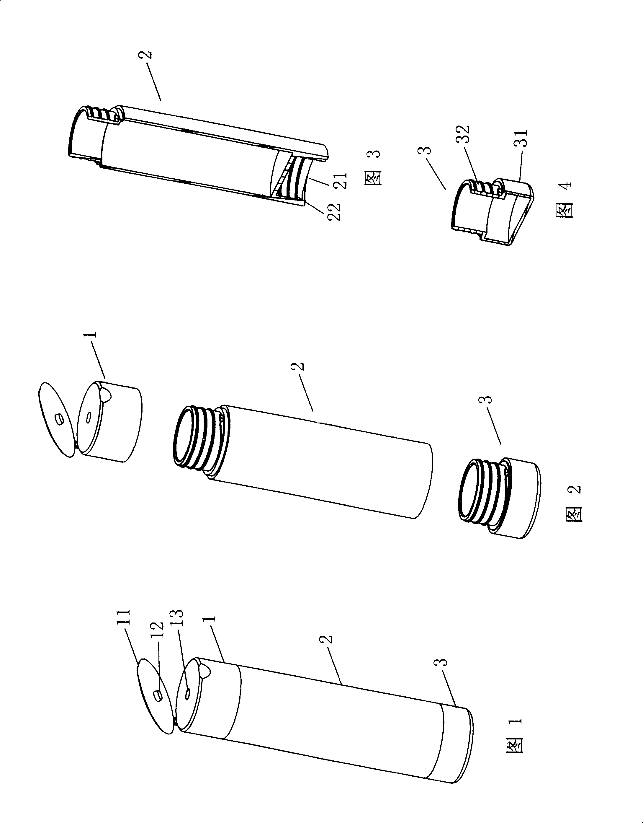
[0023] As shown in Figures 1-4, the combination container of Embodiment 1 includes a bottle body 2 and a bottle cap 1, the bottle cap 1 and the mouth of the bottle body 2 are screwed together, and the lower edge of the side wall of the bottle body 2 extends downwards on the bottle body. A cavity 21 is formed at the bottom, and threads are set on the side wall 22 in the cavity 21; a solute reservoir 3 adapted to the diameter of the bottle body 2 is also included, and the upper half of the solute reservoir 3 is placed in the bottle body Inside the cavity 21 at the bottom and threadedly connected with the side wall 22 of the cavity.
[0024] The solute reservoir 3 includes a tubular body 31 matching the diameter of the bottle body 2 and a solute reservoir bottom extending inwardly from the lower edge of the tubular body 31 . The outer wall 32 of the upper half of the tubular body 31 is threaded.
[0025] A vertical partition may also be provided in the solute storage 3, and the v...
Embodiment 2
[0030] As shown in Figures 5-8, the combination container of embodiment 2 includes a bottle body 2 and a bottle cap 1, the bottle cap 1 and the mouth of the bottle body 2 are screwed together, and the lower edge of the side wall of the bottle body 2 extends downwards on the bottle body. A cavity 21 is formed at the bottom, and threads are set on the side wall 22 in the cavity 21; a solute reservoir 3 adapted to the diameter of the bottle body 2 is also included, and the upper half of the solute reservoir 3 is placed in the bottle body Inside the cavity 21 at the bottom and threadedly connected with the side wall 22 of the cavity.
[0031] The solute reservoir 3 includes a tubular body 31 and a diaphragm 33 arranged inside the tubular body 31. The diaphragm 33 divides the interior of the tubular body 31 into a lower cavity and an upper cavity for storing solute. The lower cavity of the tubular body 31 is Both the inner wall 32 of the half and the outer wall 34 of the upper half...
Embodiment 3
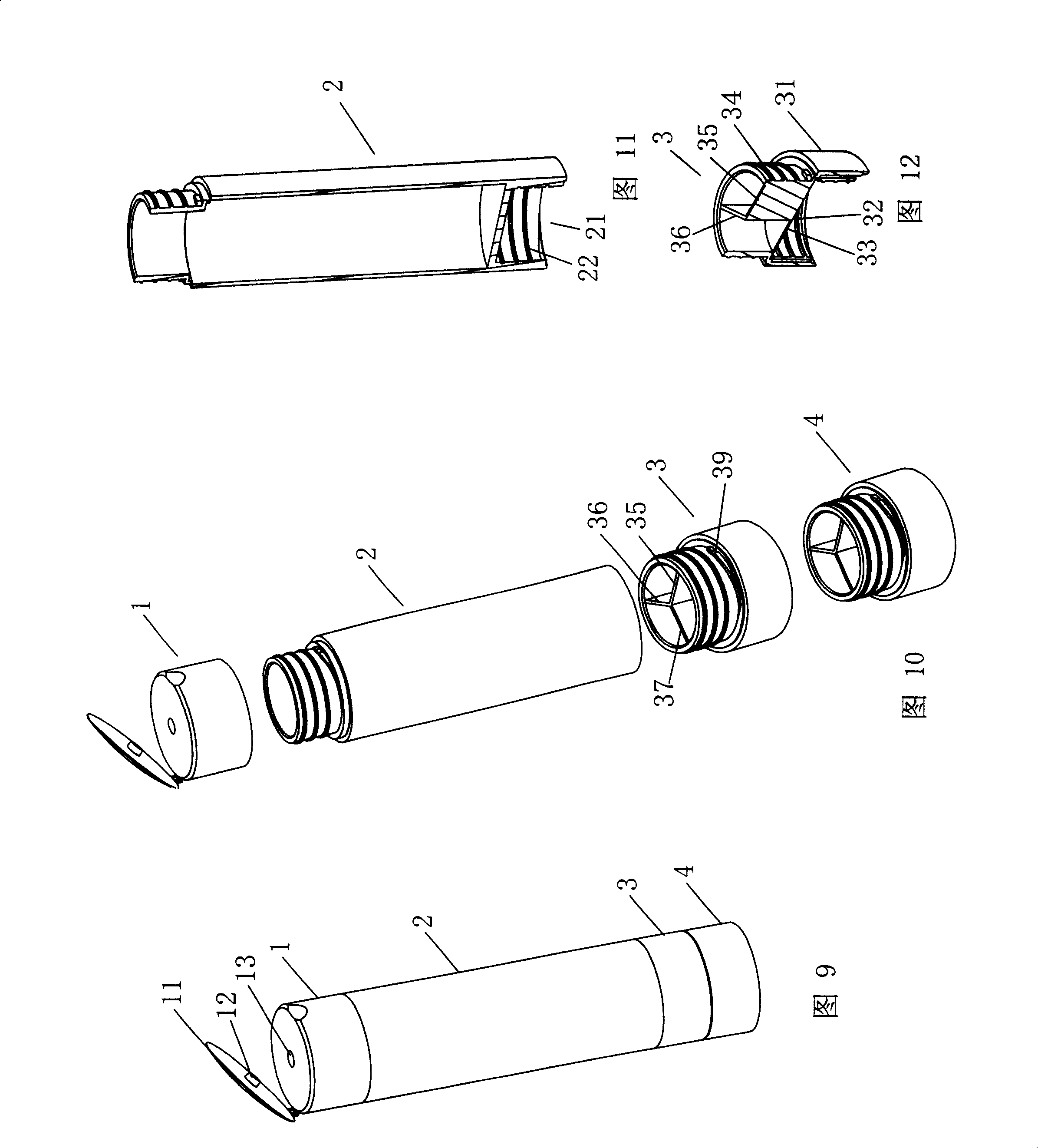
[0037] As shown in Figures 9-12, the combination container of embodiment 3 includes a bottle body 2 and a bottle cap 1, and the lower edge of the side wall of the bottle body 2 extends downwards to form a cavity 21 at the bottom of the bottle, and the inside of the cavity 21 Threads are set on the side wall 22; the bottom of the bottle body 2 is stacked with two solute reservoirs 3, 4 adapted to the diameter of the bottle body, and the upper half of the uppermost solute reservoir 3 is placed in the bottle body The cavity 21 at the bottom is screwed to the side wall 22 of the cavity, and the two adjacent solute reservoirs 3 and 4 are screwed to each other.
[0038] The solute reservoirs 3 and 4 both contain a tubular body 31 and a diaphragm 33 arranged inside the tubular body 31. The diaphragm 33 divides the interior of the tubular body 31 into a lower cavity and an upper cavity for storing solute. Both the inner wall 32 of the lower half and the outer wall 34 of the upper half...
PUM
 Abstract
Description
Claims
Application Information
 - Generate Ideas
- Intellectual Property
- Life Sciences
- Materials
- Tech Scout
- Unparalleled Data Quality
- Higher Quality Content
- 60% Fewer Hallucinations
Browse by: Latest US Patents, China's latest patents, Technical Efficacy Thesaurus, Application Domain, Technology Topic, Popular Technical Reports.
© 2025 PatSnap. All rights reserved.Legal|Privacy policy|Modern Slavery Act Transparency Statement|Sitemap|About US| Contact US: help@patsnap.com


