
Exhaust gas purifying train for spray painting workshop

A technology of exhaust gas purification device and workshop, which is applied to the device, combined device, application and other directions of coating liquid on the surface, can solve the problems of large polluting particles, inability to purify the air, air environment pollution, etc., and achieves good purification effect without causing pollution. The effect of secondary pollution

Inactive Publication Date: 2008-07-23
陈兆红
View PDF1 Cites 8 Cited by
  • Summary
  • Abstract
  • Description
  • Claims
  • Application Information

AI Technical Summary

Problems solved by technology

[0002] In the modern production process, there is the link of spraying paint on the product surface. The paint gun sprays the paint on the surface of the product. Part of the paint will fall on the surface of the product according to the requirements of the process, and the other part of the paint will rise in the air. The environment has a serious impact. People often install an exhaust fan on the painting station and exhaust it outside through the air outlet, but this will pollute the outside air environment.
Now people design various exhaust gas purification devices, such as the air purification device with the patent No. 02221241.8 announced by the State Intellectual Property Office on November 27, 2002. It is composed of a device, an air taste regulator, and an air supply pipe. Its advantages are low cost, can adjust the moisture and taste of the air, and is easy to maintain. However, it is not suitable for use in the painting workshop, because the pollution particles in the painting workshop are large and numerous, and cannot be used. Purify the polluted air well

Method used


Image

  • Exhaust gas purifying train for spray painting workshop
  • Exhaust gas purifying train for spray painting workshop

Examples


Embodiment Construction

[0018] The present invention will be further described in detail below in conjunction with the accompanying drawings and embodiments.

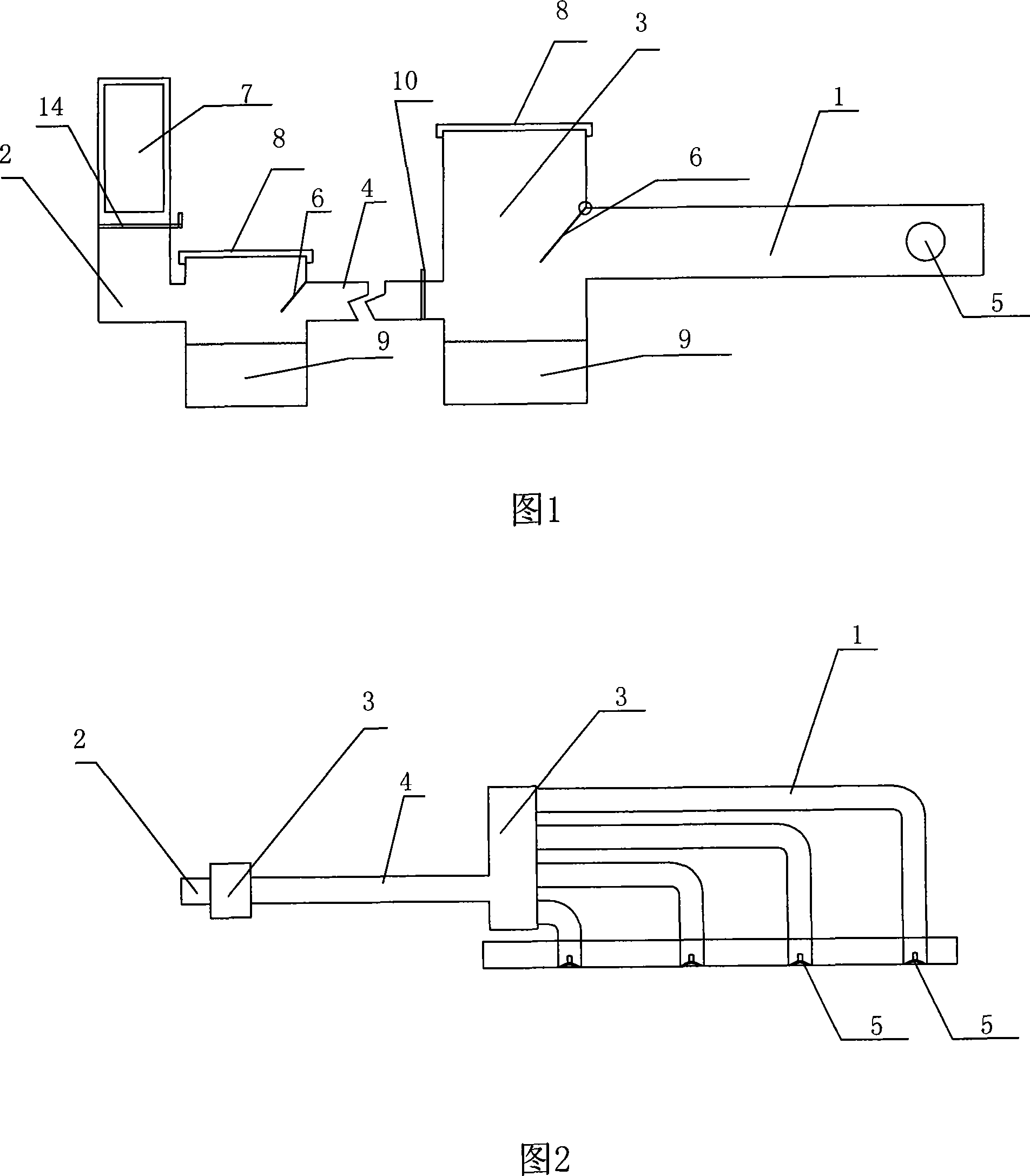
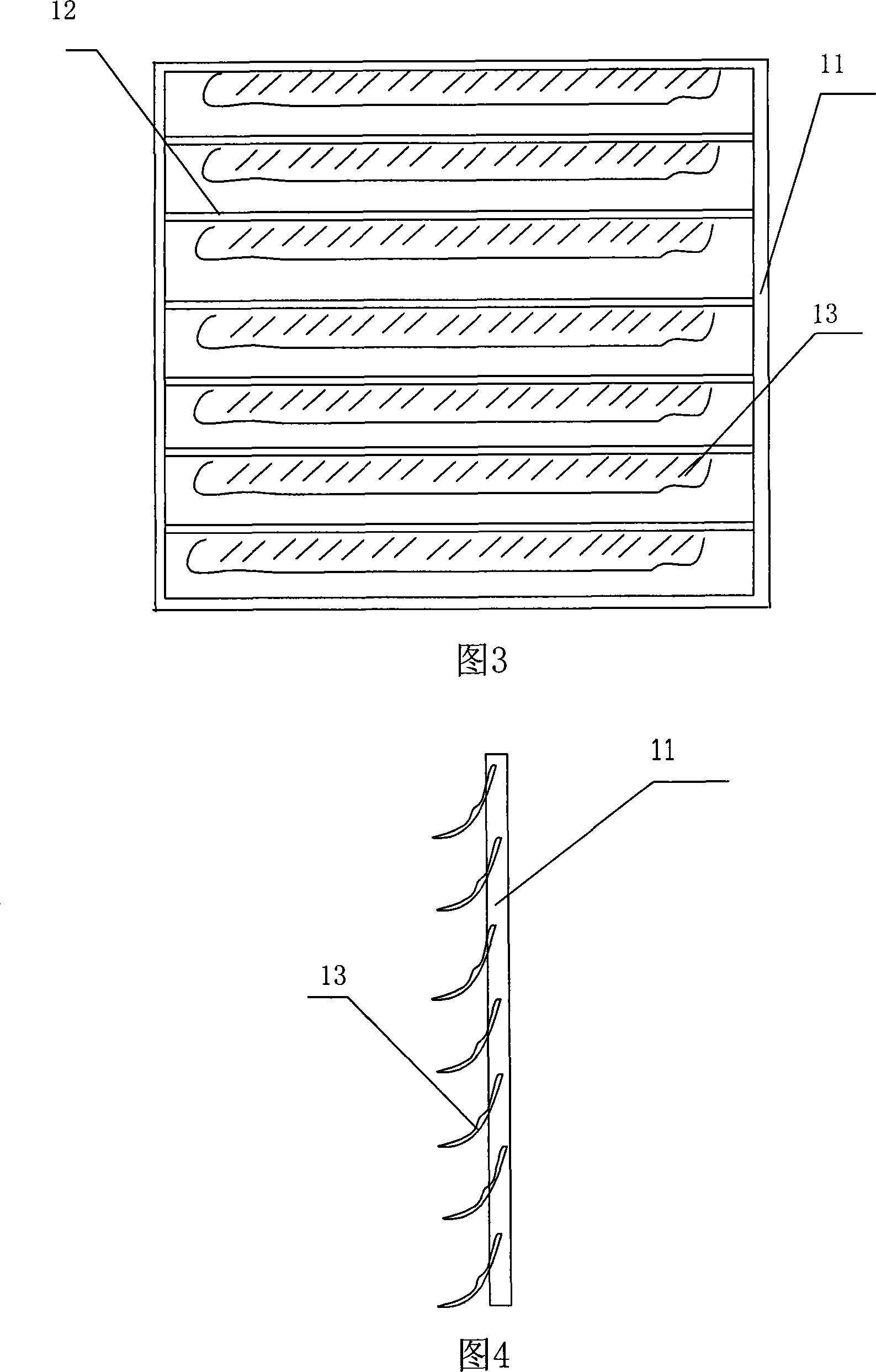
[0019] An exhaust gas purification device for a painting workshop, comprising four air inlet pipes 1 and air outlet pipes 2, two clean rooms 3 are arranged between the air inlet pipes 1 and the air outlet pipes 2, and the air ducts 4 are arranged between the clean rooms 3 Connection, the air duct 4 is placed with a dust-absorbing curtain 10, the dust-absorbing curtain 10 includes a frame 11, a crosspiece 12 and a dust-absorbing cloth 13, the crosspiece 12 is arranged in the frame 11, and the dust-absorbing cloth 13 is hung on the crosspiece 12 Above, the end of the air inlet pipe 1 corresponding to the painting station is provided with an exhaust fan 5, and the other end of the air inlet pipe 1 communicates with the clean room 3, and the air inlet of the clean room 3 is provided with a wind board 6, and the air board 6 The upper end of the upp...


PUM


Abstract

The invention discloses an exhaust gas purification device used for paint shops, which comprises at least more than one air-supply lines and more than one discharge pipes. The invention is characterized in that at least one decontamination room is arranged between the air-supply line and discharge pipe; the decontamination rooms are connected by air channels; a vacuum curtain is placed on the air channel; wherein, the vacuum curtain comprises a frame, a crosspiece and a piece of vacuum cloth. The crosspiece is arranged inside of the frame; the vacuum cloth is hung on the crosspiece; an exhaust fan is arranged at one end of the air-supply line which is corresponding to the painting position; the other end of the air-supply line is communicated with the decontamination room. The air intake of the decontamination room is provided with an air foil, the upper end of which is movably connected on the wall of decontamination room, while the lower end is hung in the air. The discharge pipe is provided with a plasma air cleaner, the top of which is provided with a cover; the lower part of which is provided with a pool where an ultrasonic atomizer is arranged. The invention has the advantages of purifying the air inside the painting room without polluting the air indoor and outdoor.

Description

technical field [0001] The invention relates to an exhaust gas purification device, in particular to an exhaust gas purification device for a painting workshop. Background technique [0002] In the modern production process, there is the link of spraying paint on the product surface. The paint gun sprays the paint on the surface of the product. Part of the paint will fall on the surface of the product according to the requirements of the process, and the other part of the paint will rise in the air. The environment has a serious impact. People often set up an exhaust fan on the painting station and exhaust it outside through the air outlet, but this will pollute the outside air environment. Now people design various exhaust gas purification devices, such as the air purification device with the patent No. 02221241.8 announced by the State Intellectual Property Office on November 27, 2002. It is composed of a device, an air taste regulator, and an air supply pipe. Its advanta...

Claims


Application Information

Patent Timeline
IPC IPC(8): B05B15/12B08B15/00B01D50/00F24F7/00
Inventor 陈兆红
Owner 陈兆红
Learn More