
High electric current density electron emitter material containing zirconium tungsten base and production method thereof

An electron emitter, high current density technology, applied in the discharge tube solid thermionic cathode, electrode system manufacturing, discharge tube main electrode, etc. The effect of improved density and emission uniformity, uniform pore distribution, and narrow pore size distribution

Inactive Publication Date: 2008-07-16
NANJING UNIV OF TECH
View PDF0 Cites 4 Cited by
  • Summary
  • Abstract
  • Description
  • Claims
  • Application Information

AI Technical Summary

Problems solved by technology

The currently developed method is to add Cr2O to the traditional barium tungsten cathode substrate (the composition weight ratio of Cr2O3 is 1-20 %, tungsten powder is 80-99%), SiO2, Sc2O3 and other rare earth oxides and metal iridium, rhenium, etc. Electron emitters, but still can not meet the requirements of high emission current density of high-power tubes

Method used


Image

  • High electric current density electron emitter material containing zirconium tungsten base and production method thereof

Examples


Embodiment 1

[0017] 1) Use tungsten powder with an average particle size of 3.39 μm, anneal in a hydrogen furnace at 1200 ° C, and pass through a 80-mesh sieve after crushing;

[0018] 2) Weigh 96g of tungsten powder and 4g of zirconia with an average particle size of 200nm and grind together for 24h;

[0019] 3) Take 2g of the mixed powder and place it in a Φ7.5mm high-precision mold for pre-molding with a pressure of 70MPa. The preformed green body is isostatically pressed, the forming pressure is 350MPa, the holding time is 30s, and the pressed cathode green body is formed;

[0020] 4) Sinter in a hydrogen furnace at 1700°C for 3 hours; take it out and process it into a porous zirconium-tungsten matrix of Φ3×1.5mm;

[0021] 5) Place in aluminate powder, immerse in a hydrogen atmosphere at 1650°C for 5 minutes, remove the floating salt after immersion, and obtain an electron emitter;

[0022] 6) Heater is installed to make cathode;

[0023] 7) Test the emission performance of the cath...

Embodiment 2

[0025] 1. Use tungsten powder with an average particle size of 3.39 μm to anneal in a hydrogen furnace at 1700 ° C, and pass through an 80-mesh sieve after crushing;

[0026] 2. Weigh 98g of tungsten powder and 2g of zirconia with an average particle size of 400nm and grind together for 24h;

[0027] 3. Take 2g of the mixed powder and place it in a Φ7.5mm high-precision mold for pre-molding with a pressure of 70MPa. The preformed green body is isostatically pressed, the forming pressure is 300MPa, the holding time is 30s, and the pressed cathode green body is formed;

[0028] 4. Sinter in a hydrogen furnace at 1950°C for 1 hour; take it out and process it into a porous zirconium-tungsten matrix of Φ3×1.5mm;

[0029] 5. Put it in aluminate powder, soak it in a hydrogen atmosphere at 1750°C for 1 minute, remove the floating salt after soaking, and make an electron emitter.

[0030] 6. Install the heater and make the cathode.

[0031] 7. Test the emission performance of the ca...


PUM

PropertyMeasurementUnit
particle sizeaaaaaaaaaa

Abstract

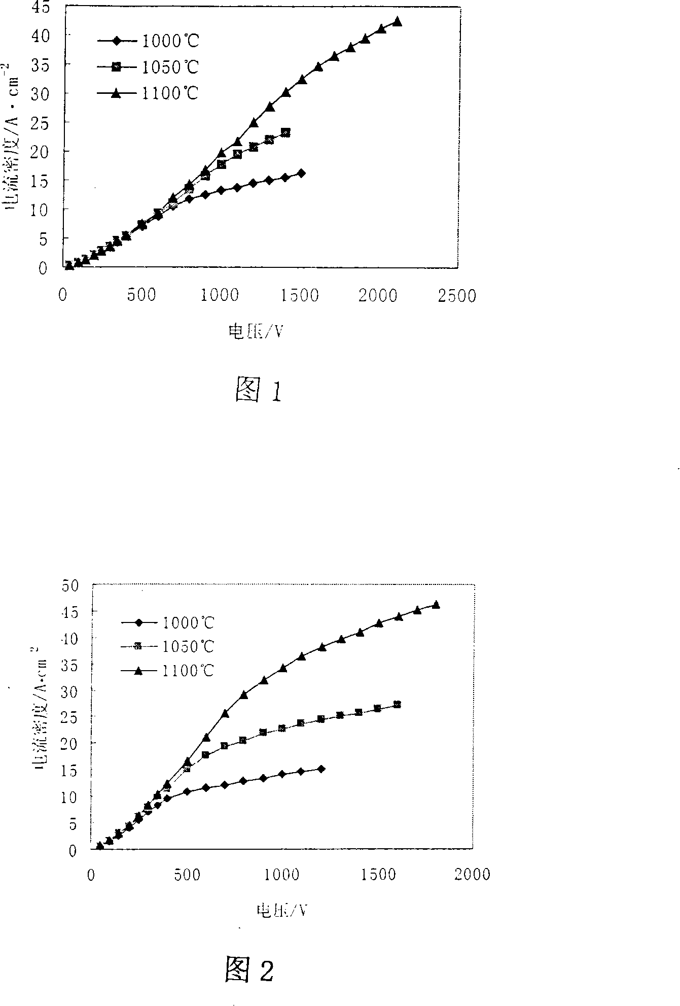
The present invention relates to a high ampere density electron emitter material and a manufacture method thereof, in particular to a high ampere density electron emitter material having zirconium-tungsten matrix and the manufacture method thereof; the basal body of the material of the invention is zirconium dioxide and tungsten; tungsten powder is weighed, annealed in a hydrogen furnace, then grinded, and filtered with a screen of 80 meshes; the filtered tungsten powder and ZrO2are grinded to be even, then molded, and disposed in aluminate powder and immersed in hydrogen circumstance; after the floating salt is removed, the electron emitter material is made. The average pore diameter of the zirconium-tungsten basal body made by the invention becomes smaller, and the pore diameter distribution becomes narrower; when the working temperature is 1050 DEG C, the current density emitted by the cathode of the invention is 1.73 to 1.86 times larger than that of the traditional barium-tungsten cathode.

Description

technical field [0001] The invention relates to a high current density electron emitter material and a preparation method, in particular to a zirconium-tungsten-based high current density electron emitter material and a preparation method, and belongs to the technical field of refractory metal cathode materials containing additives. Background technique [0002] Electron emitters are the heart of vacuum electronic devices, and are widely used in various electronic information systems and equipment such as radar, electronic countermeasures, and communication telemetry and remote control. With the development of working frequency to the millimeter wave band and the miniaturization of device size, the requirements for high current density, long life and high working stability of electron emitters are particularly urgent. The currently developed method is to add Cr to the traditional barium tungsten cathode substrate 2 O (composition weight ratio Cr 2 o 3 1-20%, tungsten powd...

Claims


Application Information

Patent Timeline
Patent Type & Authority Applications(China)
IPC IPC(8): H01J1/14H01J1/146H01J9/02B22F9/00B22F3/16B22F3/26
Inventor 沈春英丘泰卢平
Owner NANJING UNIV OF TECH
Learn More