
Method for purifying ultra-vast water and purifying device

A purification device and ultra-large-scale technology, applied in chemical instruments and methods, water aeration, water/sludge/sewage treatment, etc., can solve the problems of unrecorded air compressor data, poor water lifting effect, and inability to form air bombs, etc. question

Inactive Publication Date: 2008-07-16
朱元曾
View PDF0 Cites 2 Cited by
  • Summary
  • Abstract
  • Description
  • Claims
  • Application Information

AI Technical Summary

Problems solved by technology

If these small air bubbles are fused into several medium-sized air bubbles, rising sequentially without intermittency, air bombs and plunger suction cannot be formed, and the water lifting effect is very poor.
However, the aeration chamber of the existing water pump is in the shape of a straight cylinder, which is not conducive to the merger of the small bubbles overflowing at the same time. Only by accurately controlling the output air pressure of the air compressor can these small bubbles be fused into a complete air bombs, and there is no data about air compressors recorded in the prior art
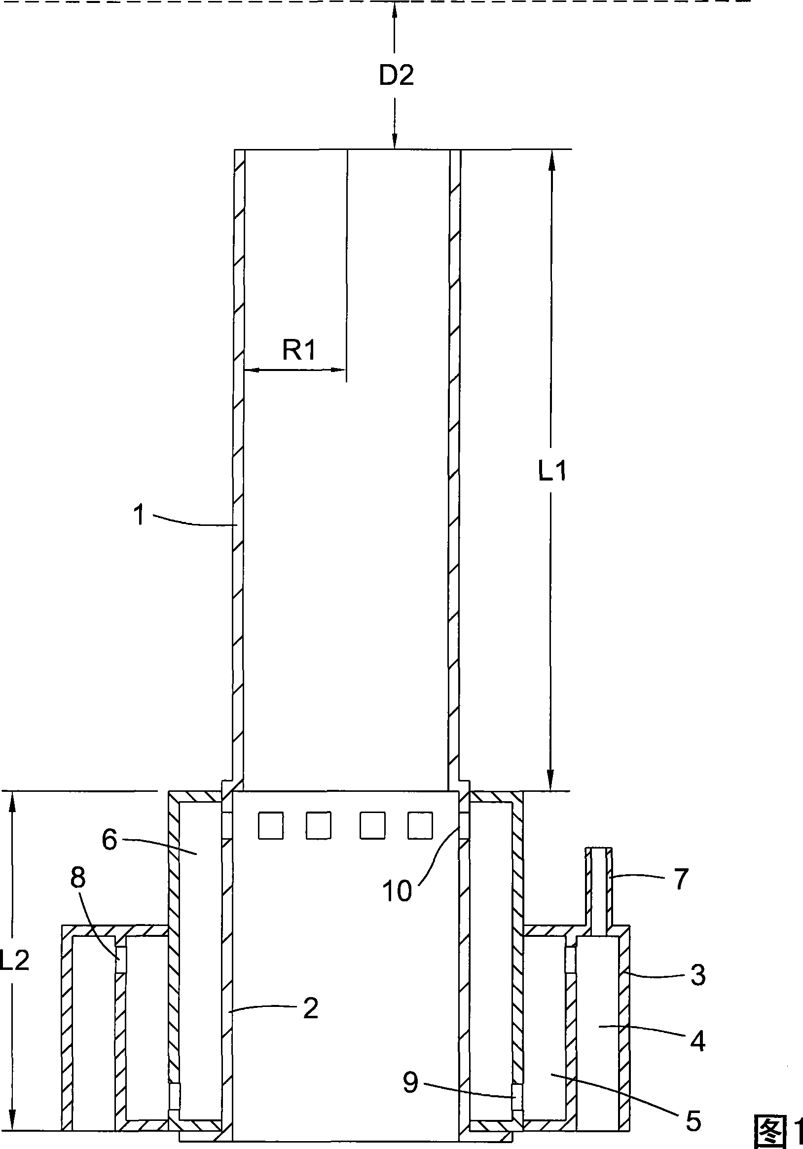
[0010] 3. The in-situ restoration of water quality using the air pumping cylinder involves the issue of energy efficiency ratio. Therefore, when using this method for in-situ restoration of water quality, some basic parameters must be determined, such as cylinder radius R1 and cylinder length L1 , the submerged depth D2 of the cylinder mouth, the height L2 of the aeration chamber, the submerged depth of the lower edge of the aeration chamber, and the air pressure output by the air compressor. There is no systematic and complete data in this regard in the prior art

Method used

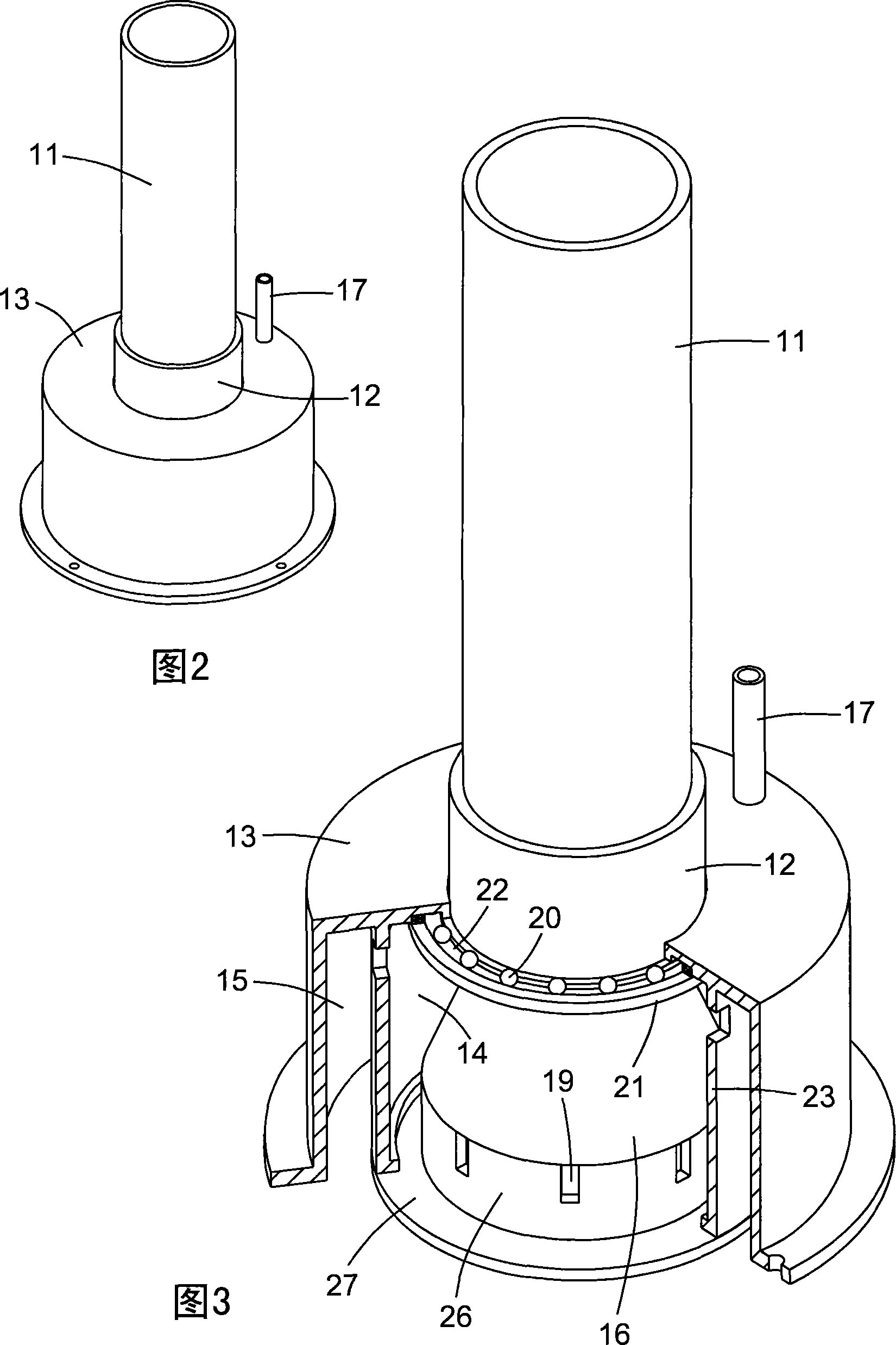
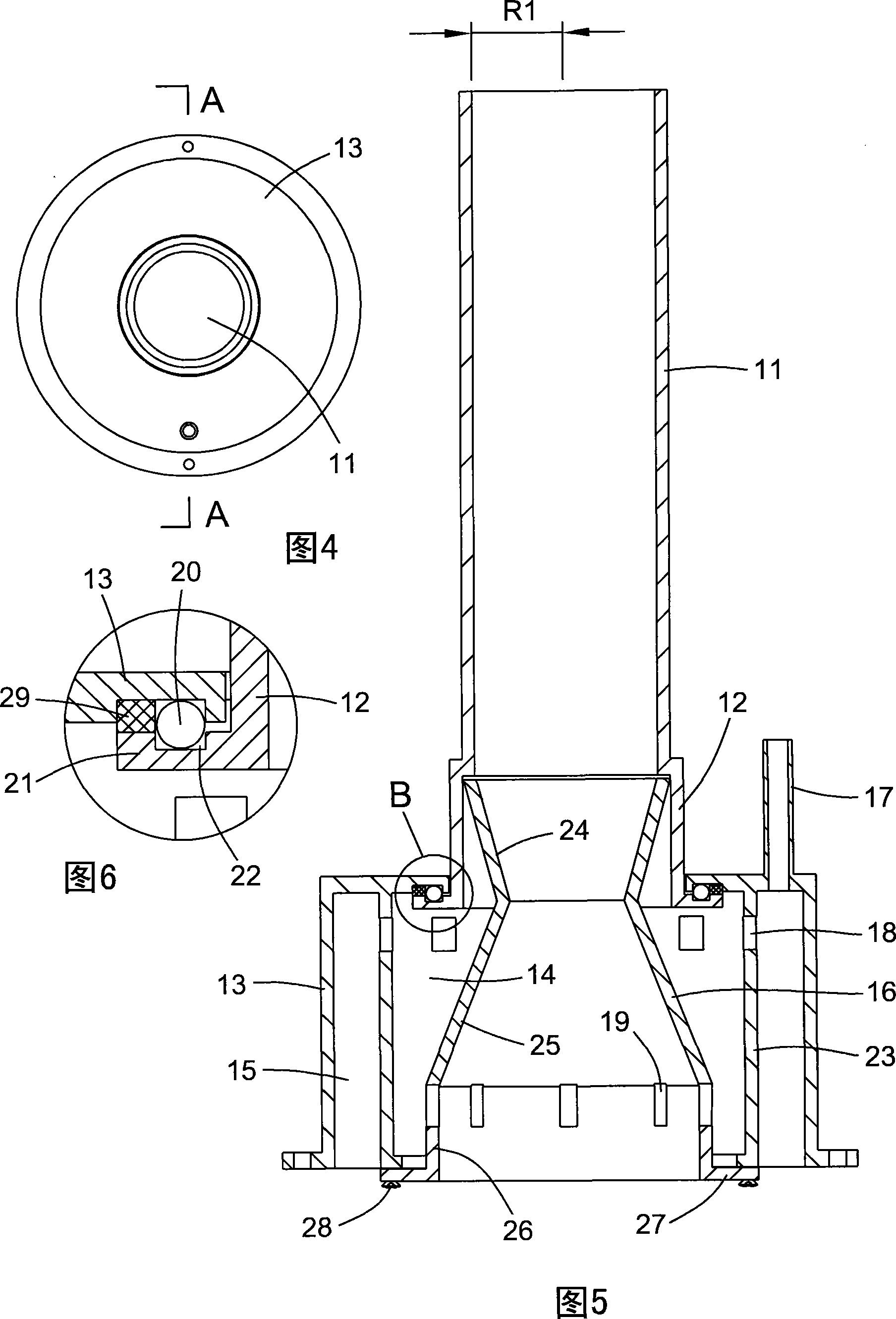

Image

  • Method for purifying ultra-vast water and purifying device
  • Method for purifying ultra-vast water and purifying device
  • Method for purifying ultra-vast water and purifying device

Examples


Embodiment 1

[0096] Embodiment 1, the present invention is a kind of purification method of super large amount of water, comprises the following steps:

[0097] Step 1. Select the target water area, which is a lake with a depth of 10 meters;

[0098] Step 2. Determine the reference water depth D1, which is 10 meters;

[0099] Step 3, arrange the purification device in the target water area, the purification device is an air pumping tube,

[0100] The cylinder body of the air pumping cylinder is composed of a straight pipe; the radius R1 of the cylinder body is 20cm;

[0101] The cylinder body length L1=50%D1=5 meters of the air pumping cylinder,

[0102] The cylinder mouth submersion depth D2=60%L1=3 meters of the air pumping cylinder,

[0103] Step 4, start the air compressor, input air into the inflatable chamber of the air pumping cylinder, the air pressure P1=150%P2 output by the air compressor, P2 is the water pressure in the inflatable chamber;

[0104] P2=ρgh, where ρ is liquid ...

Embodiment 2

[0106] Embodiment two, the present invention is a kind of super large amount of water purification method, comprises the following steps:

[0107] Step 1. Select the target water area, which is a lake with a depth of 12 meters;

[0108] Step 2. Determine the reference water depth D1, which is 12 meters;

[0109] Step 3, arrange the purification device in the target water area, the purification device is an air pumping tube,

[0110] The cylinder of the air pumping cylinder is composed of a straight pipe; the radius of the cylinder is R1=21cm;

[0111] The cylinder body length L1=49%D1=5.88 meters of the air pumping cylinder,

[0112] The submerged depth of the cylinder mouth of the air pumping cylinder D2=57% L1=3.35 meters,

[0113] Step 4, start the air compressor, input air into the inflatable chamber of the air pumping cylinder, the air pressure P1=155%P2 output by the air compressor, P2 is the water pressure in the inflatable chamber;

[0114] P2=ρgh, where ρ is liqui...

Embodiment 3

[0116] Embodiment three, the present invention is a kind of super large amount of water purification method, comprises the following steps:

[0117] Step 1. Select the target water area, which is a lake with a depth of 15 meters;

[0118] Step 2. Determine the reference water depth D1, which is 15 meters;

[0119] Step 3, arrange the purification device in the target water area, the purification device is an air pumping tube,

[0120] The cylinder body of the air pumping cylinder is composed of a straight pipe; the radius R1 of the cylinder body is 22cm;

[0121] The cylinder body length L1=48%D1=7.2 meters of the air pumping cylinder;

[0122] The mouth submerged depth D2=55%L1=3.96 meters of the air pumping cylinder;

[0123] Step 4, start the air compressor, input air into the inflatable chamber of the air pumping cylinder, the air pressure P1=160%P2 output by the air compressor, P2 is the water pressure in the inflatable chamber;

[0124] P2=ρgh, where ρ is liquid dens...


PUM

PropertyMeasurementUnit
Radiusaaaaaaaaaa
Lengthaaaaaaaaaa
Radiusaaaaaaaaaa

Abstract

The invention relates to a method for purifying a super great amount of water, which comprises the following steps: step I, the target water is selected; step II, the reference water depth(D1) is determined; when the actual depth of the target water is 10-50 meters, the reference water depth is the actual depth; when the target water depth is more than 50 meters, the reference water depth(D1) is 50 meters; step III, a purifying device, an air water-raising tunnel, is arranged in the target waters, and the tunnel body length (L1) of the air water-raising tunnel is 30 percent-50 percent of the reference water depth(D1) of the target water; the submerged depth of the tunnel mouth (D2) of the air water-raising tunnel is 40 percent-60 percent of the tunnel body length (D1); step IV, the air is input into a pressure chamber of the air water-raising tunnel and the air pressure(P1) of an air compressor is 150 percent-200 percent of water pressure in the pressure chamber. The invention can realize convection of an upper water layer and a lower water layer as well as realize the whole circulation, thus effectively facilitating dissolved oxygen quantity in the whole waters, damaging suspension state of algae and inhibiting the growth of the algae so as to purify the water.

Description

technical field [0001] The invention belongs to the technical field of in-situ restoration of water quality. Background technique [0002] There are two types of devices used for in-situ restoration of the water quality of reservoirs and lakes: [0003] One is to arrange perforated air ducts at the bottom of the lake, and use an air compressor to input compressed air into the perforated air ducts at the bottom of the lake to generate a large number of small air bubbles in the water for aeration, thereby mixing the upper and lower water layers and increasing the concentration of dissolved oxygen in the lower water body , Improve water quality. There are many studies on laying perforated air ducts at the bottom of the lake, and the technology is relatively mature, but the efficiency of this equipment is low. [0004] The other type is to arrange air pumping cylinders in the water. The structure of the air pumping cylinders is shown in Figure 1. [0005] Please refer to Figu...

Claims


Application Information

Patent Timeline
IPC IPC(8): C02F7/00
CPCY02W10/10
Inventor 朱元曾
Owner 朱元曾
Learn More