
Three polarized transverse electromagnetic wave cell field intensity test device

A transverse electromagnetic wave and test device technology, which is applied in the field of electromagnetic compatibility test devices for high-field-strength electromagnetic fields, can solve the problems of single polarized wave, cumbersome process, and poor test reproducibility, so as to enhance reproducibility and simplify the test process , the effect of good overall performance

Inactive Publication Date: 2008-07-09
SOUTHEAST UNIV
View PDF0 Cites 12 Cited by
  • Summary
  • Abstract
  • Description
  • Claims
  • Application Information

AI Technical Summary

Problems solved by technology

[0003] But both TEM Cell and GTEM Cell can only produce a single polarized wave
The electromagnetic compatibility technical standard stipulates that the equipment under test needs to be tested in three mutually orthogonal polarization modes when conducting electromagnetic radiation susceptibility tests. For this reason, the equipment under test (EUT) To perform space flipping, the process is cumbersome and the test reproducibility is poor

Method used


Image

  • Three polarized transverse electromagnetic wave cell field intensity test device
  • Three polarized transverse electromagnetic wave cell field intensity test device

Examples


Embodiment Construction

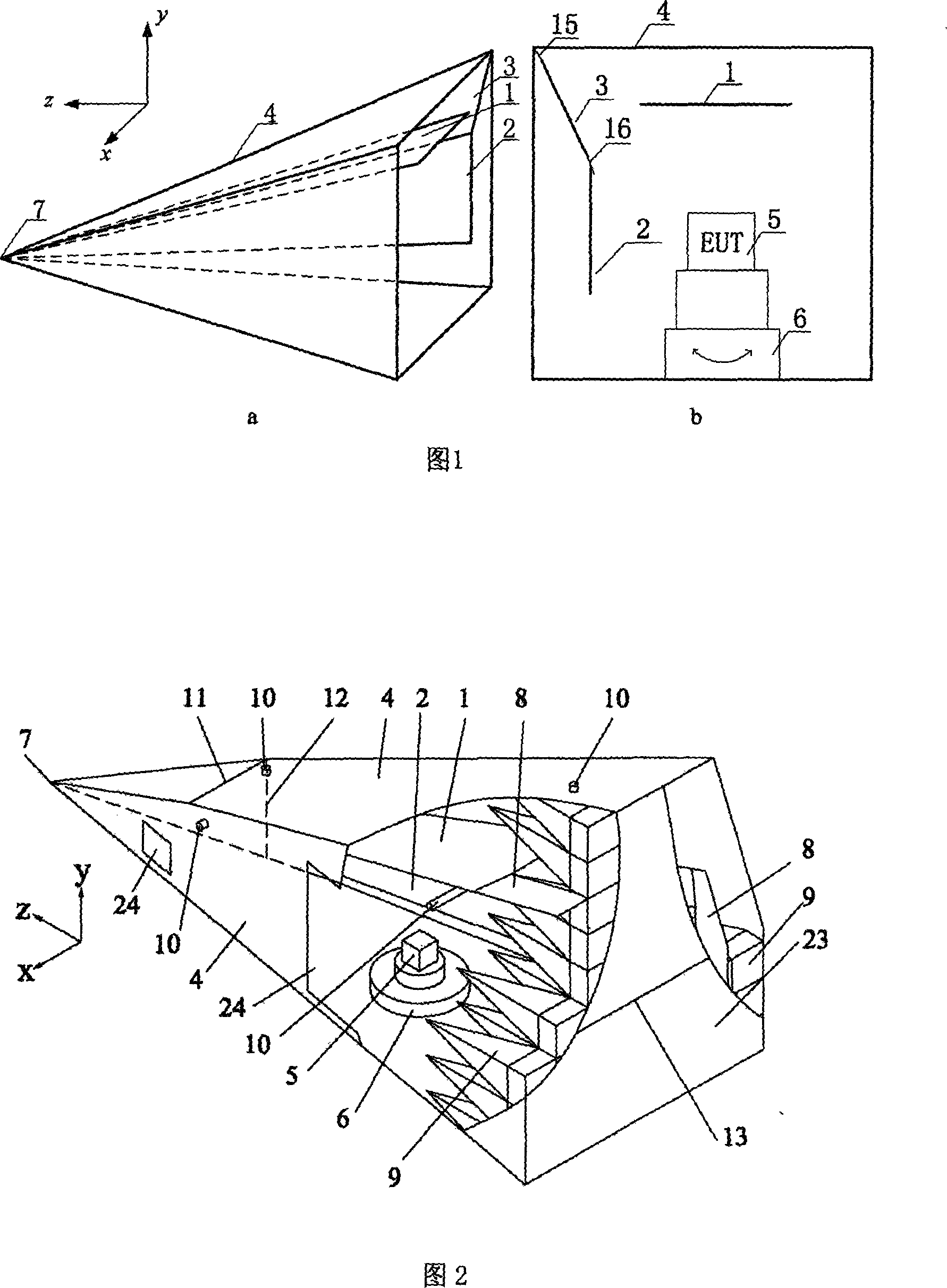
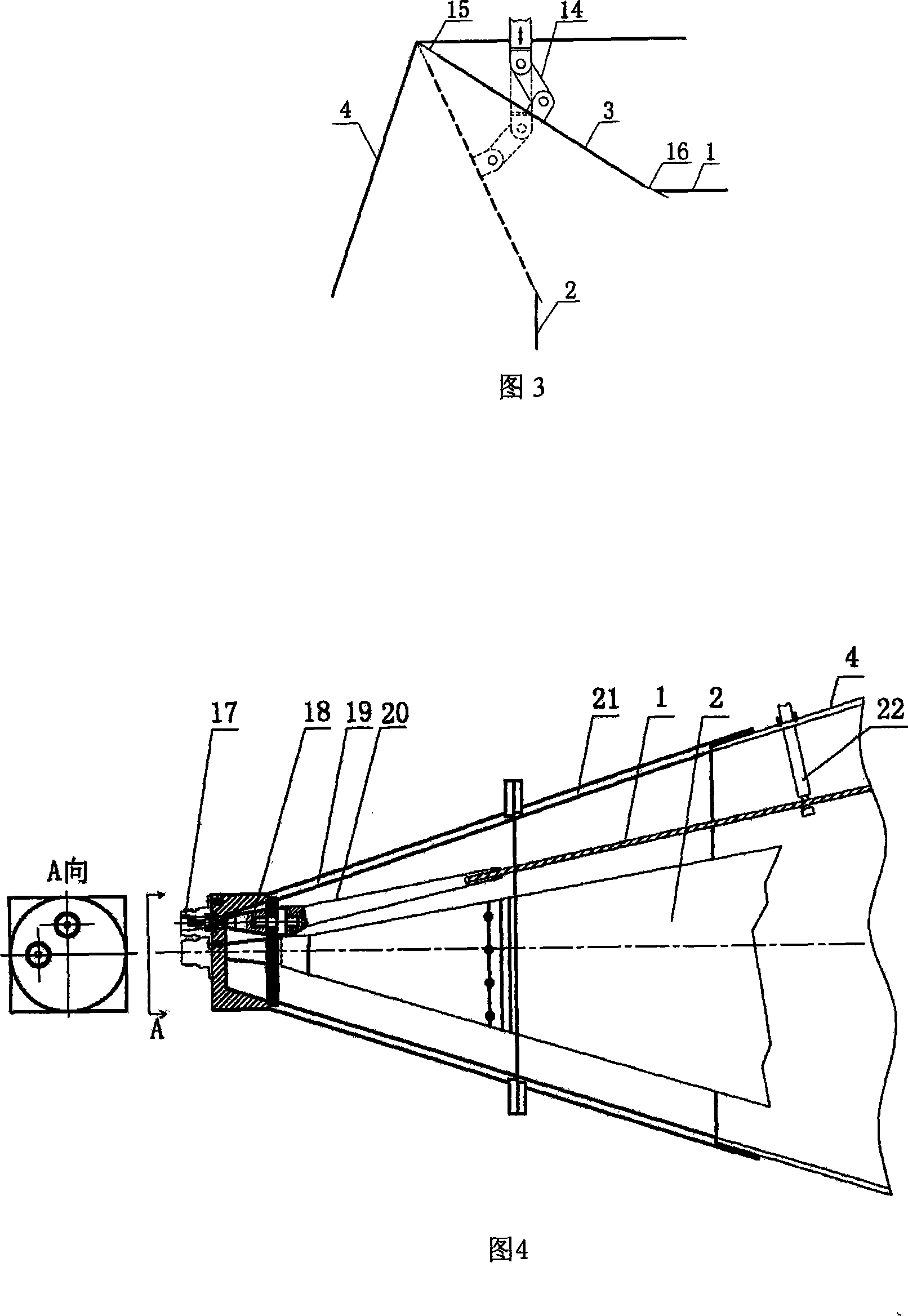
[0028] An embodiment of the present invention uses an N-type radio frequency coaxial socket 17 to feed radio frequency signals into the TTEM Cell, and the inner and outer conductors of the coaxial connector gradually expand into an axe-shaped transition block 20 and a bell mouth 19 respectively. Since the cone-shaped part 7 of the TTEM Cell has a dual-port structure and is equipped with two N-type radio frequency coaxial sockets, there are also two conical matching adjustment core blocks and two axe-shaped transition blocks inside the TTEM Cell, which are connected to the small chamber. The horizontal core plate 1 or the vertical core plate 2 is connected, and the bell mouth is connected with the main aluminum plate 4 of the outer conductor. The overall shape of the test device is a gradually expanding pyramid-shaped cavity, and the terminal is closed by an aluminum plate 23; the input end of the test device, that is, the cone-shaped part 7 has two input coaxial sockets 17, and th...


PUM


Abstract

A triple-transverse electromagnetic cell field intensity tester is an electromagnetic compatible tester capable of producing triple effect, which has a frequency coverage range superior to 10 kHz to 1 Ghz and can be used for testing radiation sensitivity and electromagnetic radiation of electronic equipment. A housing at a taper top portion (7) of the tester is expanded to form a bell mouth (19) and gradually changes to a pyramidal cavity, and the terminals are sealed by an aluminum plate (23). The tester has a double-port input structure, i.e. two coaxial plugs (17) are arranged on the taper top, and the inner conductors of the two coaxial plugs (17) are sequentially expanded to form a tapered matching adjusting core block (18) and an axe-shaped transition block (20), which are respectively connected with a trapeziform horizontal core plate (1) and a trapeziform vertical core plate (2) separated from but orthogonal to each other to form two plate-shaped inner conductors. The terminals of the inner conductors are matched with each other through a non-inductance resistor array (8) and a pyramidal wave absorbing material (9). Large-area grounding switching between the horizontal and the vertical core plates can be achieved by adopting a connection rod and a swing lapped plate, thus ensuring high-frequency grounding performance.

Description

Technical field [0001] The invention is an electromagnetic compatibility test device capable of generating a high-field electromagnetic field with a three-polarization effect, and the frequency coverage is better than 10kHz-1GHz. It can be used for electromagnetic radiation sensitivity test of electronic equipment. It belongs to the technical field of transverse electromagnetic wave field strength devices and electromagnetic compatibility testing. Background technique [0002] Transverse Electromagnetic Cell (TEM Cell), as an important electromagnetic susceptibility testing equipment, has been widely used in electromagnetic compatibility testing. It is a coaxial line with a special structure: the outer conductor of the coaxial line is an olive-shaped cavity with a gradually changing size, and the inner conductor is a core board with a gradually changing width. Compared with ordinary TEM cells, the structure of the GTEM (GHz TEM Cell) cell is further improved. The outer conductor ...

Claims


Application Information

Patent Timeline
IPC IPC(8): G01R29/08
Inventor 蒋全兴王桂华周忠元汤仕平景莘慧周香
Owner SOUTHEAST UNIV
Learn More