
Lifting type handcart

A lifting and trolley technology, applied in the directions of lifting frames, wheels, lifting devices, etc., can solve the problems of sliding, difficult, and inconvenient clamping of the trolley, so as to achieve convenient positioning and clamping of workpieces, and safe adjustment and disassembly. The effect of easy lifting

Active Publication Date: 2008-07-02
SHANGHAI MICRO ELECTRONICS EQUIP (GRP) CO LTD
View PDF0 Cites 19 Cited by
  • Summary
  • Abstract
  • Description
  • Claims
  • Application Information

AI Technical Summary

Problems solved by technology

[0002] At present, the known trolleys used to transport workpieces in the project have low lifting height accuracy. Generally, the lifting accuracy is less than 1mm. The trolley itself does not have a self-locking device. When the workpiece on the trolley moves, the trolley will slide. , vibration, tilt phenomenon
At the same time, the handling, movement, adjustment, lifting, and disassembly of workpieces on the cart are time-consuming, laborious, difficult, and inconvenient to operate
The workpieces on the trolley lack positioning and clamping devices, and it is inconvenient to clamp workpieces of different shapes and sizes, and the trolley does not have the function of vibration reduction

Method used


Image

  • Lifting type handcart
  • Lifting type handcart
  • Lifting type handcart

Examples


Embodiment approach

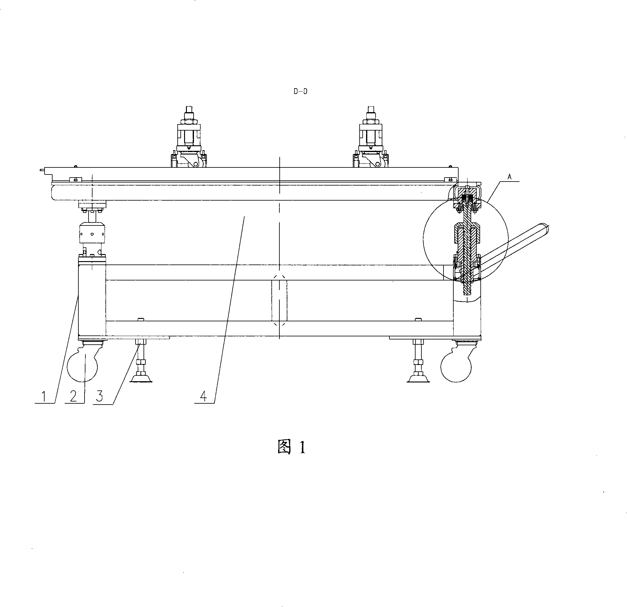
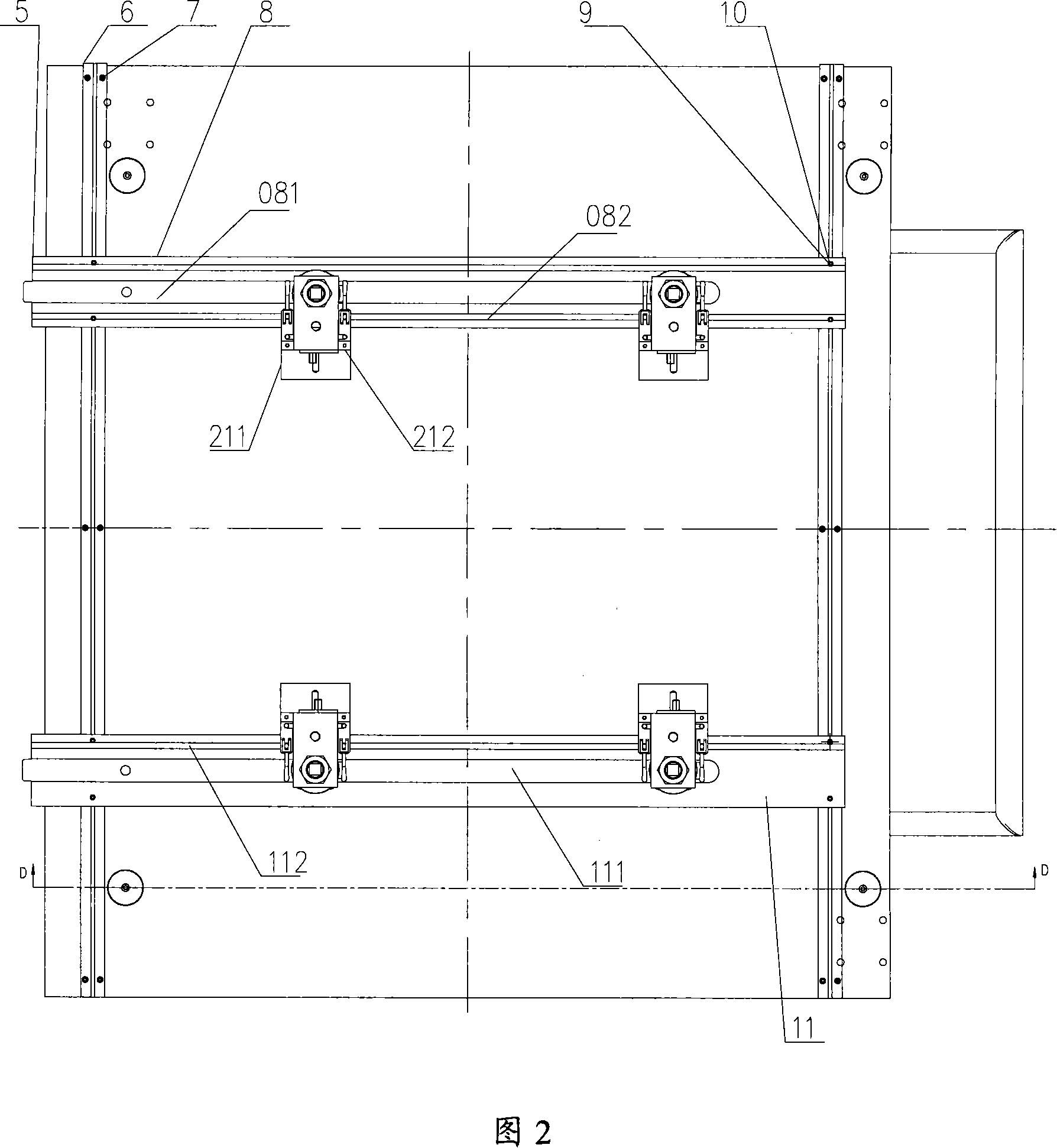
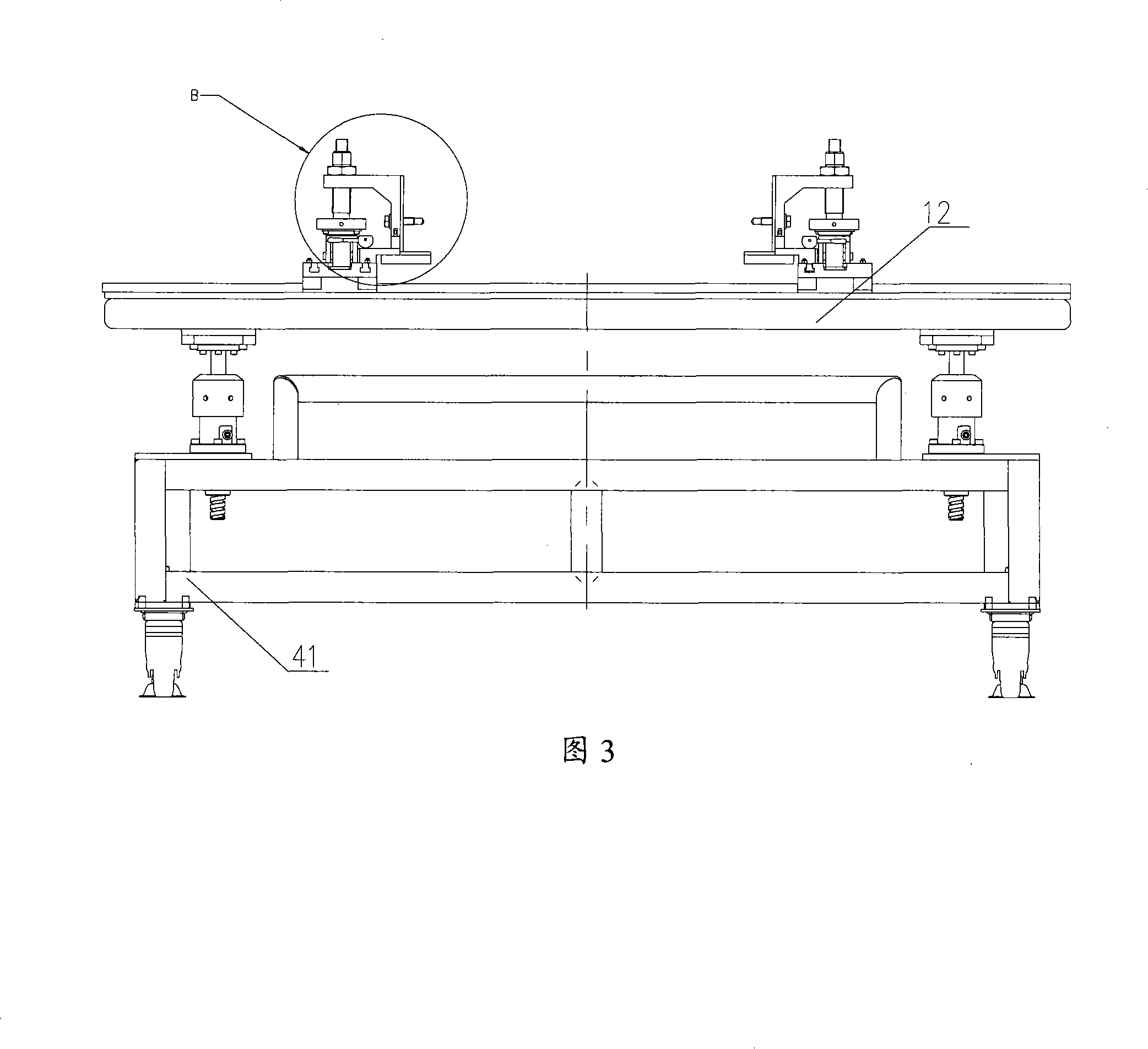
[0069] As shown in Figures 1 to 3, the present invention provides an elevating trolley, which includes a base mechanism and an upper bracket mechanism, and also includes several lifting and locking mechanisms connecting the base mechanism and the upper bracket mechanism, and is arranged on the Several workpiece lifting and locking positioning mechanisms on the upper bracket mechanism;

[0070] The base mechanism includes several casters 2 and several caster adjustment blocks 3;

[0071] The caster 2 is installed on the base 1 through a number of hexagon socket head cap screws 41, and the caster adjustment block 3 is installed on the base 1 through threads;

[0072] The upper bracket mechanism includes two guide rails 6 arranged in parallel, and also includes several sliding guide rails 5;

[0073] The guide rail 6 is fixed on the upper bracket 4 by several hexagonal cylinder head screws 7;

[0074] The sliding guide rail 5 is installed on the guide rail 6 through the trapezo...


PUM


Abstract

A lifting trammer is characterized in that the invention comprises a base mechanism and an upper supporter mechanism, as well as a plurality of lifting locking mechanisms that is connected with the base mechanism and the upper supporter mechanism and a plurality of workpiece lifting locking locating mechanisms arranged on the upper supporter mechanism. The lifting trammer provided by the invention has the advantages of adjustable lifting height, firmness, large carrying ability, no loosening, no shaking and no librating in working time, convenient workpiece assembly and disassembly and self-lock function. A guide rail is arranged on the trammer so as to be convenient for the transportation of the workpiece and simultaneously lead the workpiece to carry out linear motion according to a regulated direction. The trammer is also provided with a locating device and can load the workpieces with different shapes and dimensions.

Description

technical field [0001] The invention relates to an elevating trolley for transporting workpieces. Background technique [0002] At present, the known trolleys used to transport workpieces in the project have low lifting height accuracy. Generally, the lifting accuracy is less than 1mm. The trolley itself does not have a self-locking device. When the workpiece on the trolley moves, the trolley will slide. , vibration, tilt phenomenon. At the same time, the workpiece handling, movement, adjustment, promotion, and disassembly on the cart are time-consuming, laborious, difficult, and inconvenient to operate. The workpieces on the cart lack positioning and clamping devices, and it is inconvenient to clamp workpieces of different shapes and sizes, and the cart does not have a vibration damping function. [0003] During the integration process of the lithography machine, the installation and inspection of some components require lifting carts. At the same time, the lifting height...

Claims


Application Information

Patent Timeline
Patent Type & Authority Applications(China)
IPC IPC(8): B66F3/08B66F7/28B60B33/06
Inventor 吴荣基朱岳彬陈慧
Owner SHANGHAI MICRO ELECTRONICS EQUIP (GRP) CO LTD
Learn More