Varnish coating device and method for coating a varnish
A coating device and coating technology, which can be applied to devices, coatings, and conductors/cables that apply liquid to surfaces, etc., and can solve problems such as inapplicability and deterioration.
- Summary
- Abstract
- Description
- Claims
- Application Information
AI Technical Summary
Problems solved by technology
Method used
Image
Examples
no. 1 approach
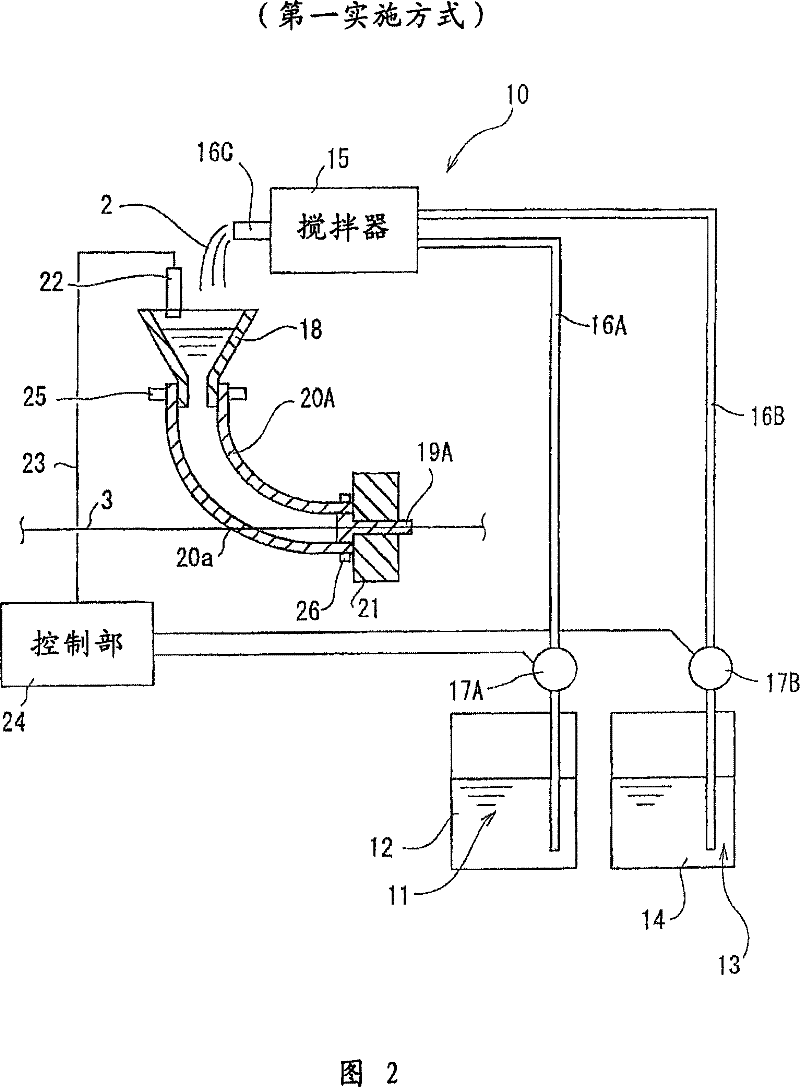
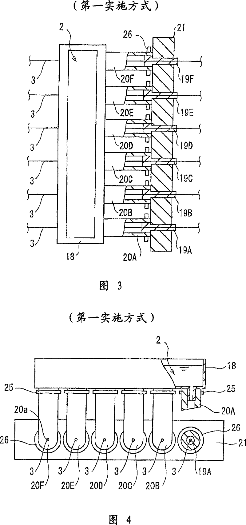
[0033] (Structure of Paint Application System)
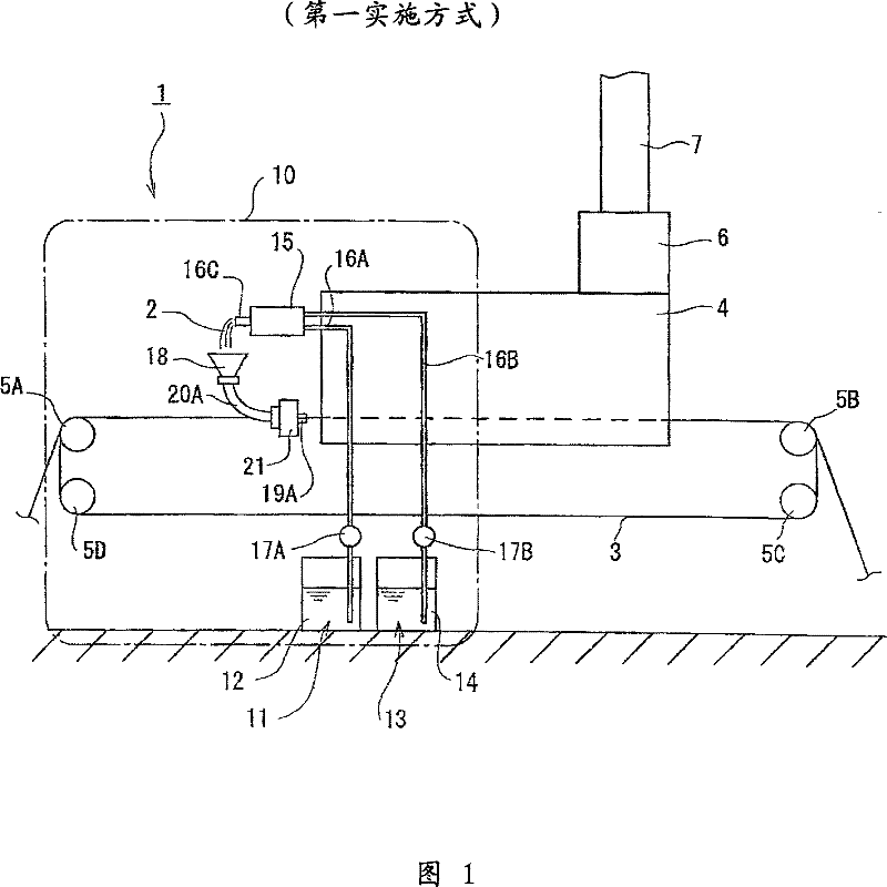
[0034] figure 1 It is a schematic configuration diagram showing the paint application system according to the first embodiment of the present invention.
[0035] The paint coating system 1 has: the paint coating device 10 that will be coated on the wire rod 3 by the paint 2 mixed by two liquids; the baking furnace 4 that is coated on the paint 2 on the wire rod 3 is dried; Pulleys (or rollers) 5A to 5D that have grooves for conveying the wire 3 on the outer peripheral surface through the paint coating device 10 and the baking furnace 4 multiple times (6 times in this case); the catalyst device installed on the baking furnace 4 6; the exhaust passage 7 installed on the exhaust port of the catalyst device 6 .
[0036] In addition, although illustration is omitted, an unillustrated winding machine and the like are provided behind the baking furnace 4 with respect to the wire rod 3 . In addition, in front of the pulley 5A, a core...
no. 2 approach
[0062] In this embodiment, in the paint application device 10 of the first embodiment, the L-shaped paint tank 30 is directly connected to the paint die instead of the pipes 20A to 20F, and other structures are the same as those of the first embodiment. In the following description, the same code|symbol is attached|subjected to the part which has the same structure and function as 1st Embodiment. In addition, in the present embodiment, although the L-shaped paint tank 30 is used, it is not limited thereto, as long as it is a paint tank having a shape that can smoothly supply the paint 2 to the coating dies 19A to 19F. The same effect can be obtained.
[0063] Figure 6 yes Figure 5 A top view of the paint tank shown, Figure 7 Viewed from the wire lead-in side Figure 6 Side view of paint tank shown.
[0064] The paint tank 30 forms a bucket shape with an upper opening. On the front wall 31 that is vertically combined with the side walls 38A and 38B and is arranged on th...
no. 3 approach
[0071] Figure 8It is a plan view showing main parts of a paint coating device according to a third embodiment of the present invention, Figure 9 yes Figure 8 A cross-sectional view of the paint application apparatus shown. Moreover, in Figure 8 In , a part of the pipeline is truncated.
[0072] In the second embodiment of the present embodiment, the paint tank 30 and the coating molds 19A to 19F are separately provided, and the two are connected by pipes 20A to 20F, and the front wall 31 of the paint tank 30 and the partition member 35 are inclined, Other structures are the same as those of the first embodiment. In addition, since the wire-passing method and coating method of the wire 3 in the paint coating apparatus 10 are the same as those of 2nd Embodiment, description is abbreviate|omitted.
[0073] According to the third embodiment, by providing the pipes 20A to 20F between the rear wall 33 of the paint tank 30 and the painting dies 19A to 19F, the amount of pain...
PUM
 Abstract
Description
Claims
Application Information
 - R&D Engineer
- R&D Manager
- IP Professional
- Industry Leading Data Capabilities
- Powerful AI technology
- Patent DNA Extraction
Browse by: Latest US Patents, China's latest patents, Technical Efficacy Thesaurus, Application Domain, Technology Topic, Popular Technical Reports.
© 2024 PatSnap. All rights reserved.Legal|Privacy policy|Modern Slavery Act Transparency Statement|Sitemap|About US| Contact US: help@patsnap.com


