Heavy-caliber base rock boring coring device

A coring device and large-diameter technology, applied in the direction of extracting undisturbed core devices, earthwork drilling and mining, etc., can solve the problems of difficult operation, time-consuming, low safety factor, etc., and achieve high coring success rate and coring efficiency Enhanced, operationally reliable results

Inactive Publication Date: 2011-04-13
长江岩土工程有限公司
View PDF0 Cites 0 Cited by
  • Summary
  • Abstract
  • Description
  • Claims
  • Application Information

AI Technical Summary

Problems solved by technology

Traditional large-diameter coring equipment requires operators to go down the well frequently. Due to the influence of groundwater, the pumping equipment does not stop when the personnel go down the well. There are many factors that affect the success of coring, such as groundwater in the hole, safety of pumping equipment in the hole, and stability of the hole wall , orifice protection, mechanical reliability, personnel operating proficiency, etc., the probability of personal accidents is extremely high, and the safety is extremely poor
It takes a lot of time to pump water. If there is a large amount of water gushing in the hole in a special formation (such as abundant confined water, large fissures, etc.), and it is impossible to pump water down, the drilling cannot continue
[0004] Traditional bedrock large-diameter drilling and coring equipment needs repeated pumping, which has low coring efficiency, poor reliability, low safety factor, and difficult operation, which is difficult to adapt to the needs of large-diameter drilling

Method used


Image

  • Heavy-caliber base rock boring coring device
  • Heavy-caliber base rock boring coring device
  • Heavy-caliber base rock boring coring device

Examples


Embodiment Construction

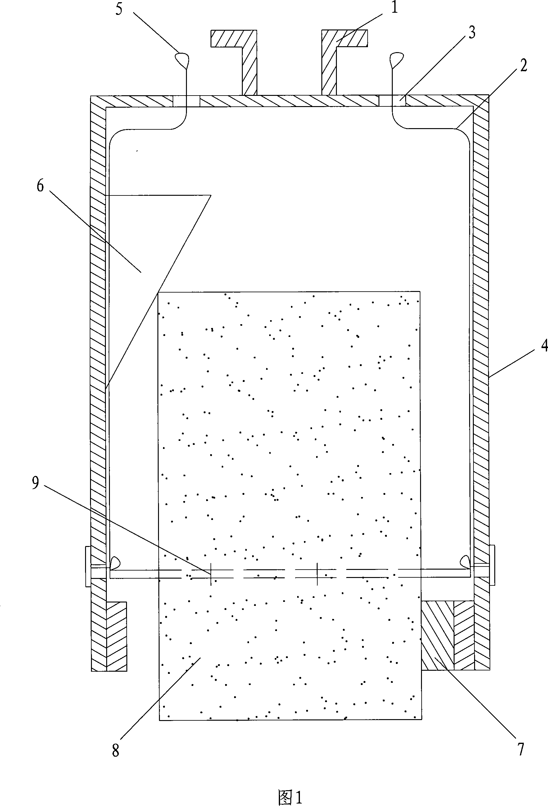
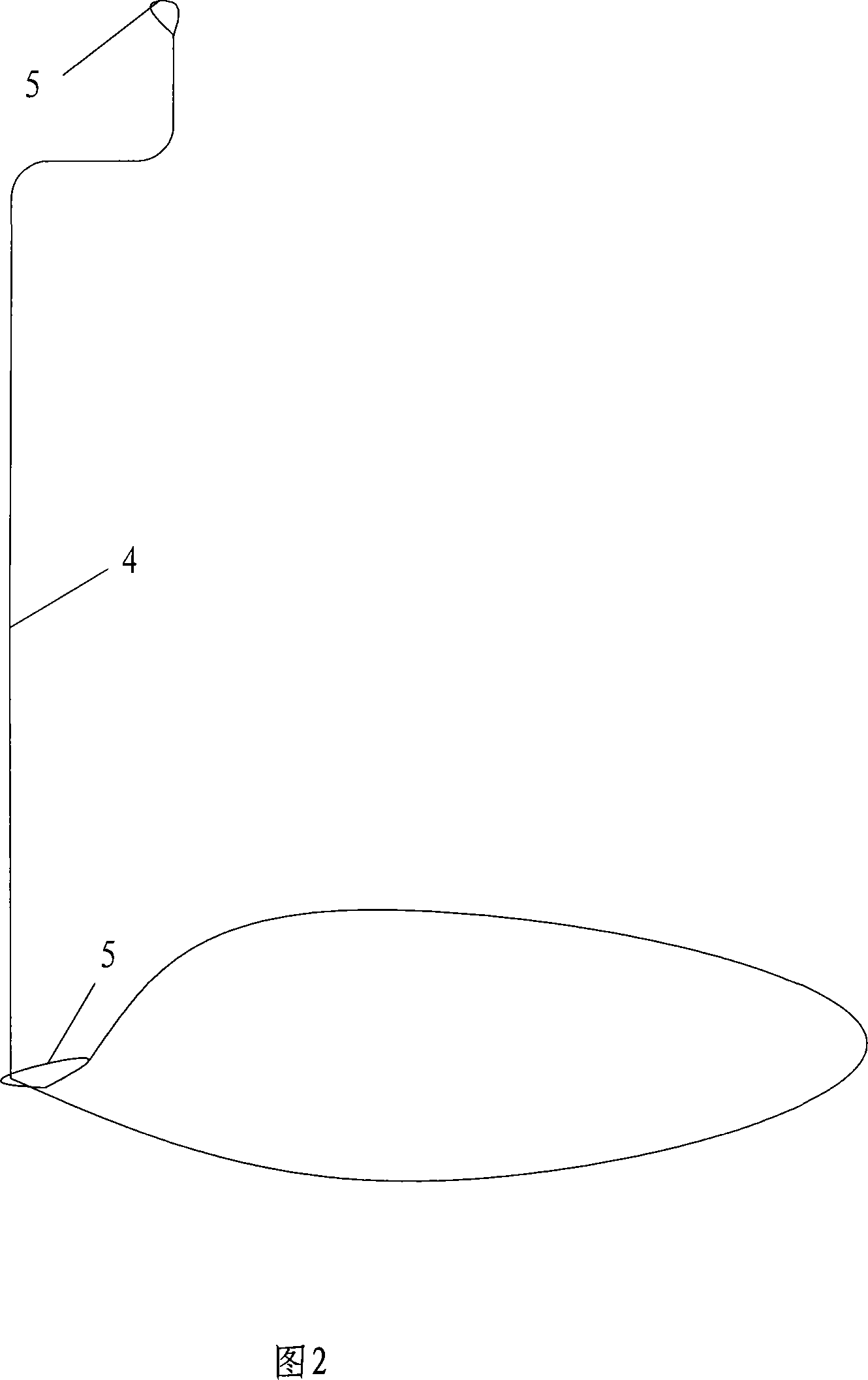
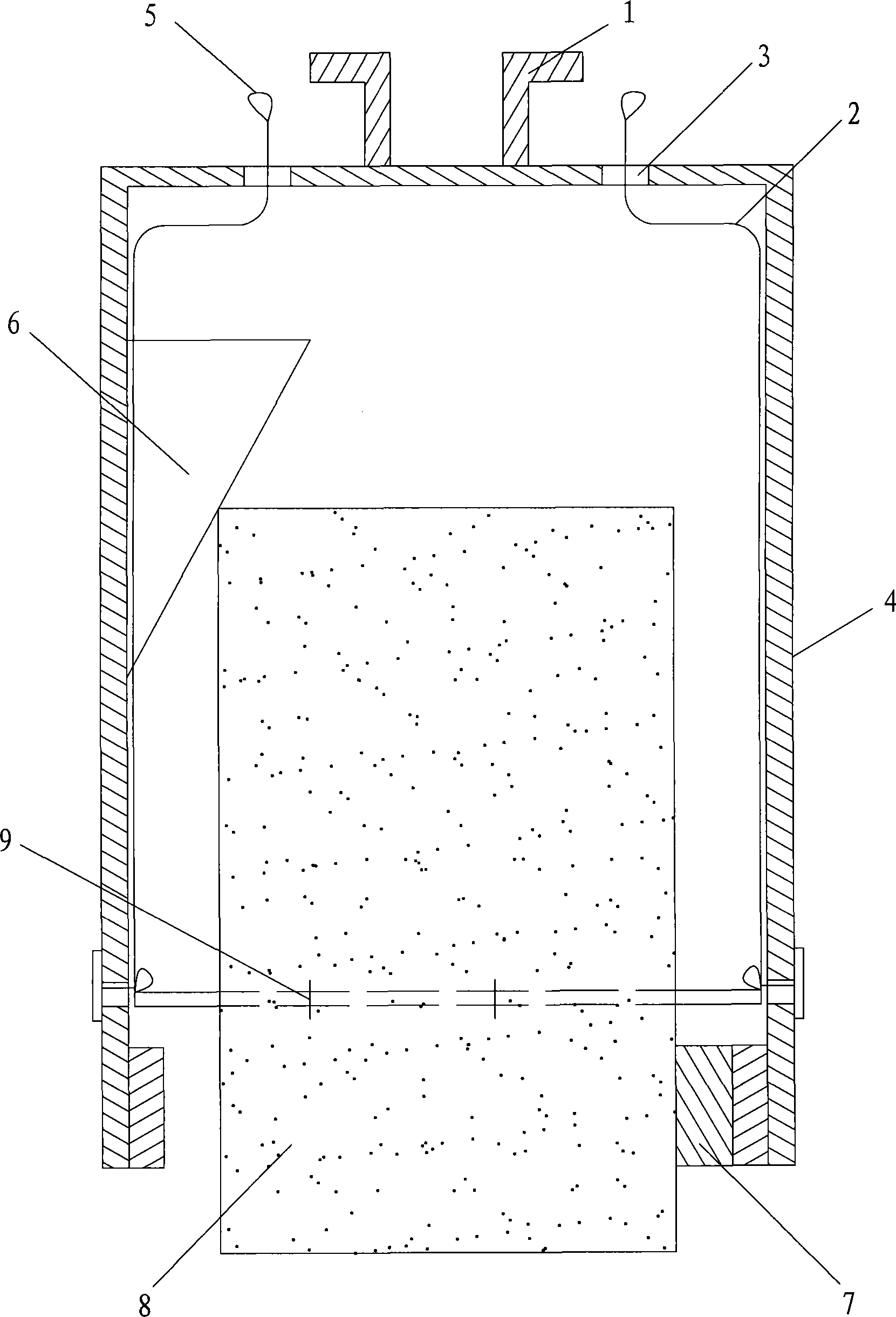
[0014] As shown in Figures 1 and 2, the large-diameter bedrock drilling and coring device of the present invention includes a connecting flange 1, a steel wire rope 2, a rope sleeve hole 3, a guiding coring cylinder 4 and a ring buckle 5, and the connecting flange 1 and the rope The casing holes 3 are all located at the top of the guiding core barrel 4, and the two ends of the steel wire rope 2 are provided with buckles 5, and also include a support block 7 and a wedge 6. One end of the steel rope 2 passes through the buckle 5 at the other end, and the steel rope 2 is another One end is arranged in the lower part of the guide coring cylinder 4 in a ring shape, and is bound on the inner wall of the guide coring cylinder 4 by a fixture 9, and one end of the steel wire rope 2 passing through the ring buckle 5 passes through the rope sleeve hole 3 and is arranged on the guide coring cylinder. Above the cylinder 4, the wedge 6 is arranged on the top of the guiding core cylinder 4, a...


PUM


Abstract

The invention discloses a heavy-caliber bedrock drilling core device which comprises an adapting flange, a wire rope, a wiring sleeve hole, a guiding core barrel and annular beckets, wherein, the adapting flange and the wiring sleeve hole are arranged on the top of the guiding core barrel; the annular beckets are arranged on both ends of the wire rope; the invention also comprises a supporting block and a wedge block; one end of the wire rope passes through annular beckets on the other end, and the other end of the wire rope forms the shape of a ring and is arranged on the lower part of the guiding core barrel and bound on the inner wall of the guiding core barrel through a fixture; one end of the wire rope which passes through the annular beckets is arranged on the upper part of the guiding core barrel after passing through the wiring sleeve hole; the wedge block is arranged on the upper part of the guiding core barrel; the supporting block is welded at the bottom of the guiding corebarrel. The heavy-caliber bedrock drilling core device of the invention does not need pumping and does not need staff to go down a well as well, thereby core efficiency is greatly improved and technical problems of long time of pumping which is repeated time after time for heavy-caliber bedrock drilling, great pumping difficulty and great downhole risk of the operation staff are solved; moreover,the invention has the advantages of simple structure, reliable operation and high core success ratio.

Description

technical field [0001] The invention relates to the scientific fields of water conservancy engineering and construction engineering, in particular to the large-diameter bedrock drilling and coring technology in the field of engineering construction. Background technique [0002] Large-diameter drilling is widely used, such as engineering drilling, building concrete pile foundation, mine power station shaft, sewage treatment well, underground oil depot and special test engineering drilling, etc. [0003] The working process of traditional large-diameter bedrock drilling and coring equipment is as follows: after the first round of drilling, water is pumped into the hole, a wedge is inserted to break the core, and the pumping continues. propose. Traditional large-diameter coring equipment requires operators to go down the well frequently. Due to the influence of groundwater, the pumping equipment does not stop when the personnel go down the well. There are many factors that af...

Claims


Application Information

Patent Timeline
Patent Type & Authority Patents(China)
IPC IPC(8): E21B25/10
Inventor 范子福付绍南武营军张涛付志伦胡梅生张精卫
Owner 长江岩土工程有限公司
Why Eureka
Try Eureka