Soldering tin stove pot port with separating slice
A technology of solder furnace and separator, which is applied in the direction of assembling printed circuits with electric components, can solve the problems of affecting welding quality, high equipment requirements, and pressure fluctuations affecting welding quality, so as to improve work efficiency, reduce equipment requirements, and reduce soldering The effect of surface diffusion
Inactive Publication Date: 2008-06-11
SUZHOU MINGFU AUTOMATIC SCI & TECH
View PDF0 Cites 0 Cited by
- Summary
- Abstract
- Description
- Claims
- Application Information
AI Technical Summary
Problems solved by technology
This kind of structure requires that the PCB board and the spout maintain a relatively constant distance during the soldering process of the solder furnace. A slight change in the distance will direc
Method used
View moreImage
Smart ImageViewing Examples

Examples
Example Embodiment
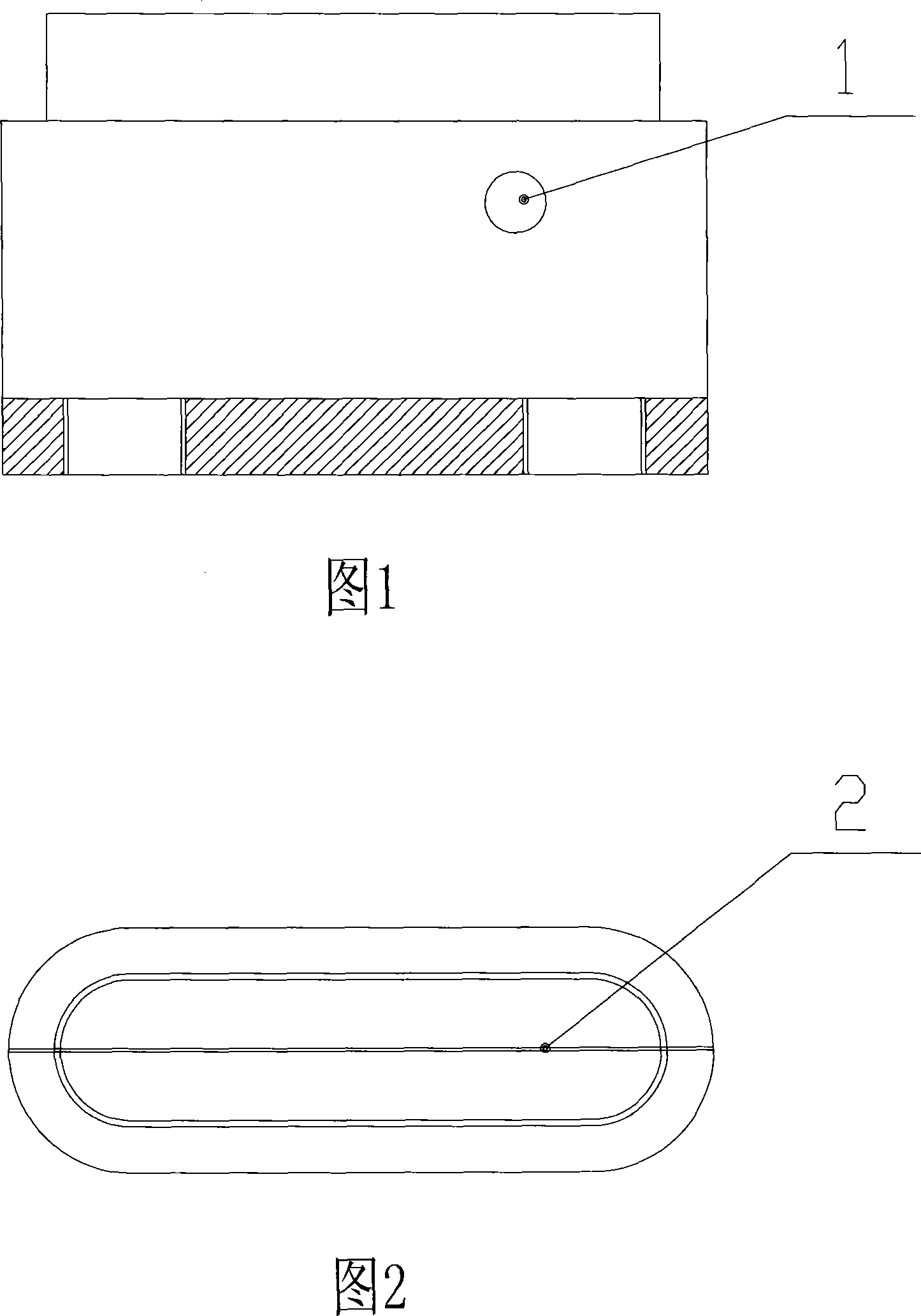
[0012] As shown in Fig. 1 and Fig. 2, there is at least one overflow tin hole 1 on the periphery of the pot mouth. The number of overflow holes 1 can be set according to the welding area and the pressure of the pot mouth. A separator 2 is provided at the tin outlet of the spout. The height of the tin overflow hole 1 from the tin outlet of the pot mouth is 2-10 mm, and the shape of the tin overflow hole 1 is circular.
Login to View More PUM
 Abstract
The invention relates to a solder furnace used for PCB board soldering, in particular to a solder furnace pot mouth, wherein, at least one tin overflow hole is arranged around the pot mouth; the tin outlet of the pot mouth is provided with a separation sheet; the tin overflow hole is 2mm to 10mm above the tin outlet of the pot mouth, and is in the shape of a rotundity. Through the arranged tin overflow hole for tin overflow, the invention can directly place a PCB board on the pot mouth, thereby reducing equipment requirements and increasing work efficiency; moreover, the invention effectively reduces the influence on PCB board welding quality caused by pot mouth pressure fluctuation as well as the quality defects such as weld face diffusion and insufficient welding due to too high pressure or too low pressure during PCB board welding; in addition, the invention can adjust the tin pressure on the pot mouth.
Description
technical field [0001] The invention relates to a tin furnace component used for PCB board soldering, in particular to a tin furnace spout. Background technique [0002] When the usual wave soldering adopts the spout structure to weld the PCB board above the spout, the spout of the tin furnace is designed as a flat mouth. Keep a certain distance, on the one hand to ensure that the tin liquid sprayed from the spout can weld the electrical components on the upper PCB board, and at the same time ensure that the tin liquid sprayed from the spout can be discharged from the spout in time to prevent the spout from Excessive pressure will affect the welding quality. This kind of structure requires that the PCB board and the spout maintain a relatively constant distance during the soldering process of the solder furnace. A slight change in the distance will directly affect the welding quality and have high requirements for the equipment. In addition, the spout The pressure fluctuat...
Claims
Login to View More Application Information
Patent Timeline
 IPC IPC(8): H05K3/34
Inventor 庄春明
Owner SUZHOU MINGFU AUTOMATIC SCI & TECH
Features
- R&D
- Intellectual Property
- Life Sciences
- Materials
- Tech Scout
- Unparalleled Data Quality
- Higher Quality Content
- 60% Fewer Hallucinations
Learn More Browse by: Latest US Patents, China's latest patents, Technical Efficacy Thesaurus, Application Domain, Technology Topic, Popular Technical Reports.
© 2025 PatSnap. All rights reserved.Legal|Privacy policy|Modern Slavery Act Transparency Statement|Sitemap|About US| Contact US: help@patsnap.com