
Monitoring system and monitoring method

A monitoring system and control technology, applied in the communication field, can solve the problems of difficult command operation, high construction cost, inability to use the monitoring function of terminal equipment, etc., and achieve the effect of rich content and form and good compatibility

Inactive Publication Date: 2014-04-09
ZTE CORP
View PDF4 Cites 0 Cited by
  • Summary
  • Abstract
  • Description
  • Claims
  • Application Information

AI Technical Summary

Problems solved by technology

[0005] (1) If a dedicated network is used, for example, the current wired Ethernet network and wireless WIFI network, when the number of terminal devices is large, it is necessary to establish a complete network terminal device and various auxiliary network terminal devices to ensure the smooth flow of the network, etc. , and, due to the heavy daily network maintenance work and huge construction costs, it is not suitable for popularization and use in commercial and civilian areas of ordinary scale;
[0006] (2) In the case of using the monitoring terminal equipment with SMS sending to monitor the remote terminal equipment, there are limitations in the graphic and text operation interface, and only some simple menu operations can be performed, so it is very difficult to realize complex command operations ; and the terminal equipment is generally not universal, and the existing terminal equipment cannot be used to realize the monitoring function;
[0007] (3) When the monitoring terminal system does not contain large-scale data storage terminal equipment (for example, database), it is impossible to realize the preservation of historical data in the long-term monitoring process
[0008] So far, no effective solutions have been proposed for the above problems

Method used


Image

  • Monitoring system and monitoring method
  • Monitoring system and monitoring method
  • Monitoring system and monitoring method

Examples


Embodiment Construction

[0026] System embodiment

[0027] In this embodiment, a monitoring system is provided. The system realizes the monitoring of terminal equipment by combining WEB and SMS network system.

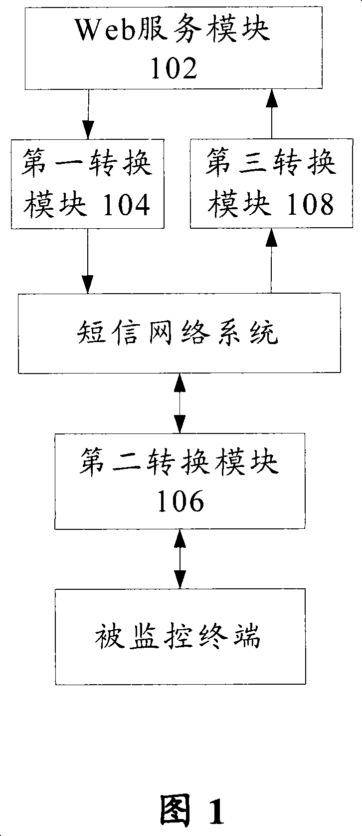
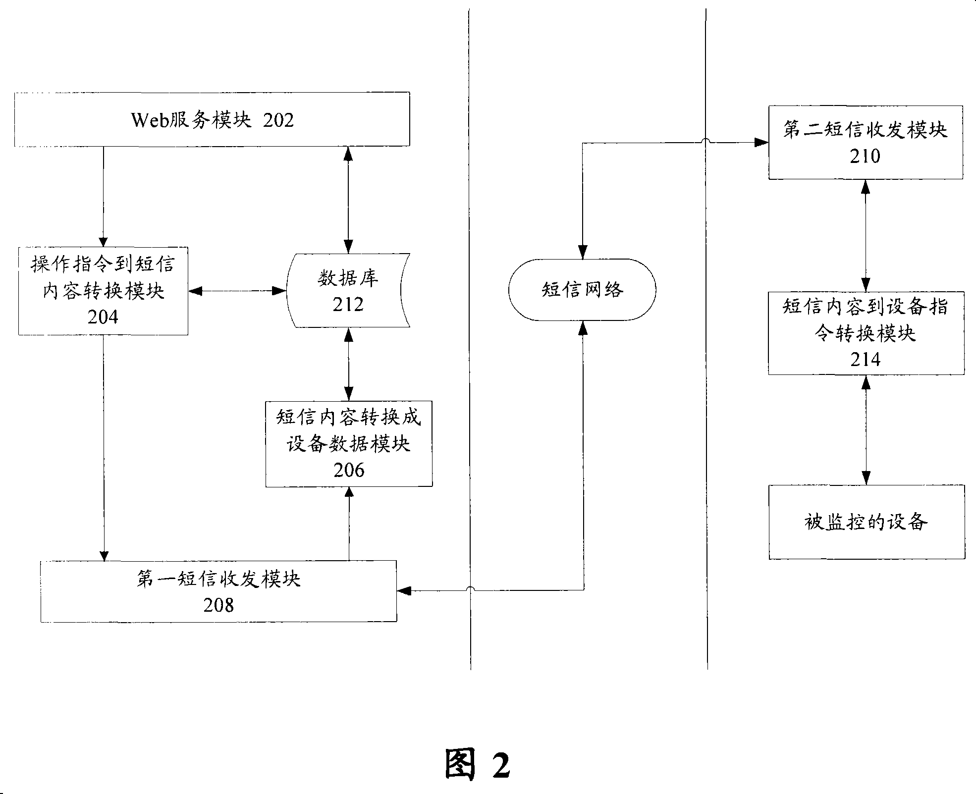
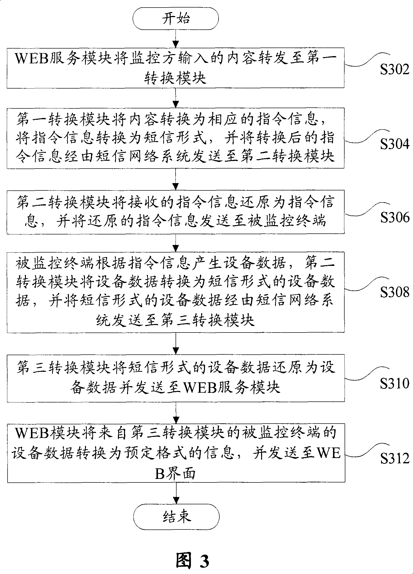
[0028] Such as figure 1 As shown, the monitoring system according to the system embodiment of the present invention includes: WEB service module 102, which is used to forward the content input by the monitoring party to the first conversion module 104, and transfer the equipment data of the monitored terminal from the third conversion module 108 Convert the information into a predetermined format and send it to the WEB interface; the first conversion module 104 is used to convert the content from the WEB service module 102 into corresponding instruction information, and convert the instruction information into a short message form, and send the short message form The instruction information is sent to the second conversion module 106 via the short message network system; the second conversio...


PUM


Abstract

A monitoring system comprises: a WEB service module which relays the contents inputted by a monitoring party to a first conversion module, and converts the equipment data of a monitored terminal from a third conversion module into information with predetermined format and sends the information to a WEB interface; the first conversion module which converts the contents from the WEB service module into corresponding instruction information, and converts the instruction information into short messages and sends the instruction information in form of short messages to the second conversion module through a short message network system; the second conversion module which reduces the instruction information in form of short messages into the instruction information and sends the reduced instruction information to the monitored terminal, and converts the equipment data generated by the monitored terminal according to the instruction information into the equipment data in form of short messages and sends the equipment data in form of short messages to the third conversion module through the short message network system; and the third conversion module which reduces the equipment data in form of short messages into the equipment data and sends the reduced equipment data to the WEB service module.

Description

technical field [0001] The present invention relates to the communication field, and in particular, to a monitoring system and a monitoring method. Background technique [0002] The terminal monitoring service refers to the remote processing services such as status monitoring, remote control, and data collection performed by the user on the terminal equipped with the command transceiver module through the network as the bearer. The user sends the instruction to the terminal device, and the terminal device performs corresponding operations according to the instruction, and then the terminal device transmits the corresponding operation result or data to the instruction sender, and the instruction sender displays the operation result or the information reported by the terminal device according to the feedback data. data. [0003] At present, there are mainly two ways for users to monitor terminals. One is to monitor terminal equipment through user-specific networks (for exampl...

Claims


Application Information

Patent Timeline
Patent Type & Authority Patents(China)
IPC IPC(8): H04L12/26H04L29/06H04W4/18G08C17/02
Inventor 孙仁峰崔磊何兵黎昱
Owner ZTE CORP
Learn More