Transmitting antenna device of transient electromagnetic equipment

A transmitting antenna and transient electromagnetic technology, applied in the transient electromagnetic field, can solve the problems of poor coupling between transmitting and receiving electromagnetic fields, inconvenient installation and disassembly, time-consuming and laborious measurement, etc., and achieve the effects of high detection accuracy, convenient measurement and simple structure.

Inactive Publication Date: 2010-10-13
SHANDONG UNIV
View PDF4 Cites 0 Cited by
  • Summary
  • Abstract
  • Description
  • Claims
  • Application Information

AI Technical Summary

Problems solved by technology

The structure and performance of the antenna in the transient electromagnetic equipment device is an important factor affecting the advanced accuracy of this technology. At present, the transmitting antenna basically has no fixed structure, and it is a four-line frame temporarily built on site. There are poor receiving signals, difficulty in moving, and transmission Disadvantages such as poor coupling with the receiving electromagnetic field, time-consuming and laborious measurement, inconvenient installation and disassembly, and unsightly appearance

Method used


Image

  • Transmitting antenna device of transient electromagnetic equipment
  • Transmitting antenna device of transient electromagnetic equipment
  • Transmitting antenna device of transient electromagnetic equipment

Examples


Embodiment 1

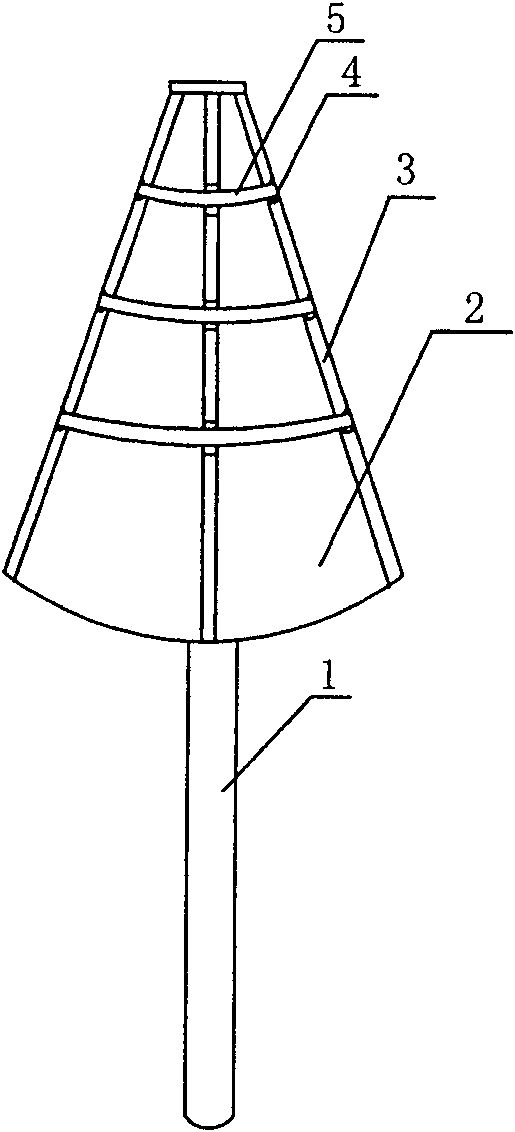
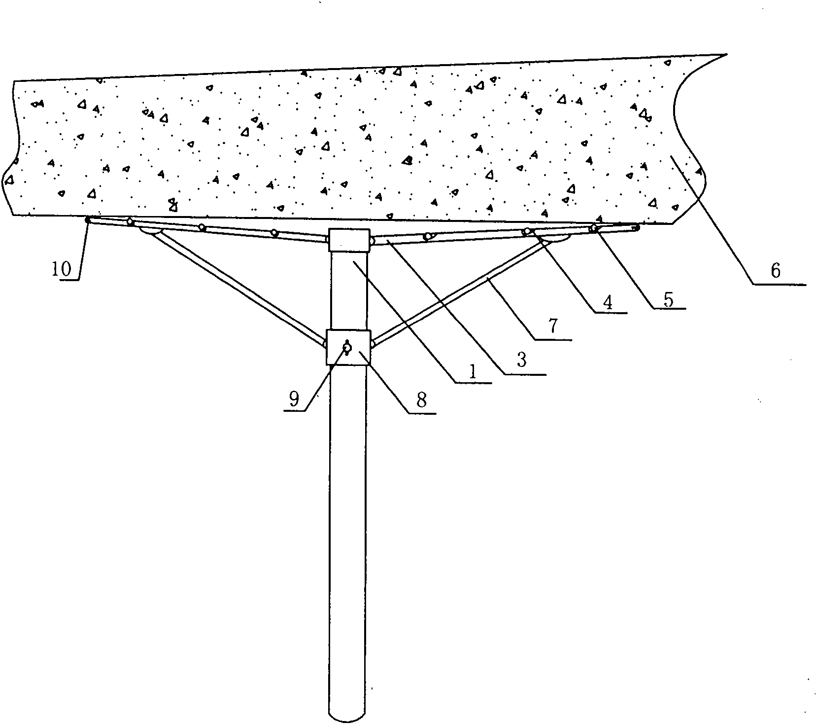
[0014] Example 1: figure 1 , figure 2 Among them, one end of eight evenly distributed skeletons 3 is hinged to the top of the fixed rod 1, one end of the support 7 is hinged to the guide ring 8 sleeved on the fixed rod 1, and the other end is hinged to the skeleton 3, and the upper part of the skeleton 3 is provided with three grooves Shaped barb 4, lead wire 5 passes through the relative groove shape barb 4 on the adjacent skeleton 3 successively to form a concentric annular regular octagonal mesh structure, and the umbrella surface 2 is arranged on the lower surface of the skeleton 3, and the umbrella surface 2 is A layer of metal reflective mesh. Skeleton 3 top is provided with longitudinal opening, and longitudinal opening is provided with conducting wire, and this conducting wire is concentric with the conducting wire of the concentric annular regular octagonal network structure that passes through groove-shaped barb 4, forms launcher jointly.

[0015] Umbrella surface...

Embodiment 2

[0016] Embodiment 2: Different from Embodiment 1, there are six skeletons 3 and they are evenly distributed. There are two groove-shaped barbs 4 on the skeleton 3. The barbs 4 form a concentric annular equilateral triangle network structure.

Embodiment 3

[0017] Embodiment 3: The difference from Embodiment 1 is that the wires 5 are spaced through the opposite groove-shaped barbs 4 on the adjacent skeleton 3 to form a concentric annular regular quadrilateral network structure.


PUM


Abstract

The invention relates to a transmitting antenna device of transient electromagnetic equipment, which comprises a fixed link, a support, a framework and an umbrella cover. One end of the framework is hinge jointed with the top of the fixed link, one end of the support is connected with the fixed link and the other end is hinge jointed with the framework. At least one barb in groove shape is equipped on the surface of the framework, and lead is provided in the barb in groove shape of bordering framework completely or alternatively. The lead on the framework forms a concentric ring structure andthe umbrella cover is set on the lower surface of the framework. The umbrella cover in the invention can be pulled down at other times and overturned on the fixed link like an umbrella. When using, aknighthead can fold up the umbrella in the shape of an umbrella to form the umbrella cover opposite to the crag into a hollow cabochon. Face the umbrella cover to the surface of the crag, the electropult formed by reticulate lead can generate electromagnetic wave which can penetrate the terrane and return when meet with a hollow, then accepted by accepting device. The invention is characterized by simple structure, high exploration precision, anti-jamming, convenient measurement, easy carrying, flexibility and high precision for measuring coupling, etc.

Description

technical field [0001] The invention relates to a transient electromagnetic technology, in particular to a transmitting antenna device of a transient electromagnetic device. Background technique [0002] There are a large number of tunnel projects in the field of water conservancy, hydropower and transportation in my country. Geological disasters in tunnel engineering are the key factors restricting tunnel construction. Often due to the unknown geological conditions in front of the tunnel, unpredictable geological disasters often occur, such as water inrush, mud inrush, collapse, rock formation, etc. Explosion and harmful gases, etc. Once a disaster occurs, the normal construction will be interrupted due to the destruction of machinery and equipment, flooding of tunnels, or severe casualties and huge economic losses, and even some underground projects will be forced to suspend construction or reroute. Transient electromagnetic equipment can be used for advanced prediction of...

Claims


Application Information

Patent Timeline
Patent Type & Authority Patents(China)
IPC IPC(8): G01V3/12H01Q1/08
Inventor 李术才李树忱蒋奇苏茂鑫张庆松
Owner SHANDONG UNIV
Why Eureka
Try Eureka