
Rotary ring bearing structure

A technology for rotating rings and rotating shafts, which is applied in the direction of rotating bearings, bearings, roller bearings, etc., and can solve problems such as unrecorded preloading

Active Publication Date: 2008-06-04
MITSUBISHI HEAVY IND LTD
View PDF5 Cites 4 Cited by
  • Summary
  • Abstract
  • Description
  • Claims
  • Application Information

AI Technical Summary

Problems solved by technology

Although it is described that the preload amount gradually increases with the insertion of rollers, it does not describe the preload amount for each row

Method used


Image

  • Rotary ring bearing structure
  • Rotary ring bearing structure
  • Rotary ring bearing structure

Examples


no. 2 example

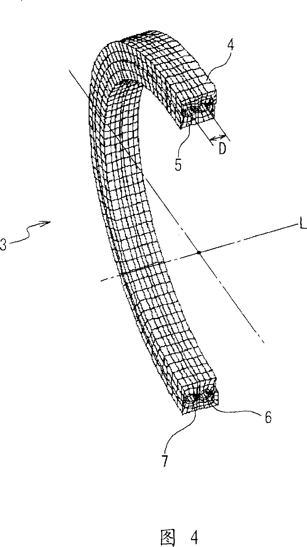
[0051] As another example of unequal load distribution, double-row spherical roller bearings are used. By adjusting the preload on the rollers, the load capacity of the bearing increases, and some uneven loads can be absorbed. Integrating the cages of the first rolling element row 6 and the second rolling element row 7 is beneficial to the uniformity (flattening) of the surface pressure. It can effectively equalize the ball load on one circumference. In order to make the ball load uniform, the rolling surface of the outer ring 4 and the rolling surface of the inner ring 5 are formed into a non-circular shape, or one of the outer ring 4 and the inner ring 5 is formed into a non-circular shape. The preload applied to the balls can make the pressure distribution on the surface of the bearing uniform (flattened).

[0052] As described above, according to the double-row slewing ring bearing of the present invention, the surface pressure difference distribution is flattened by flat...


PUM


Abstract

A slewing bearing structure comprises:an outer ring (4) having first and second circumferential outer grooves formed on an inner circumferential surface in parallel;an inner ring (5) provided on an inner side of said outer ring section and having first and second circumferential inner grooves formed on an outer circumferential surface in parallel in correspondence to said first and second circumferential outer grooves of said outer ring section (4);a first row (6) of rolling elements provided in said first circumferential outer groove of said outer ring (4) and said first circumferential inner groove of said inner ring (5); and a second row (7) of rolling elements provided in said second circumferential outer groove of said outer ring (4) and said second circumferential inner groove of said inner ring ( 5 ) ,wherein said inner ring (5) rotates via said first and second rolling element rows (6, 7) around a rotation axis in a relatively opposite direction to said outer ring (4),wherein said outer ring (4) includesa first outer ring section (8) provided with said first circumferential outer groove; anda second outer ring section (9) provided with said second circumferential outer groove;wherein said inner ring (5) includesa first inner ring section (11) provided with said first circumferential inner groove; anda second inner ring section (12) provided with said second circumferential inner groove,wherein said slewing bearing structure further comprises a first pair of side plates (13), each plate of said first pair being fitted to a side circumferential surface of said first and second outer ring sections (8, 9), respectively, and / or a second pair of side plates (13'), each plate of said second pair being fitted to a side circumferential surface of said first and second inner ring sections (11, 12), respectively.

Description

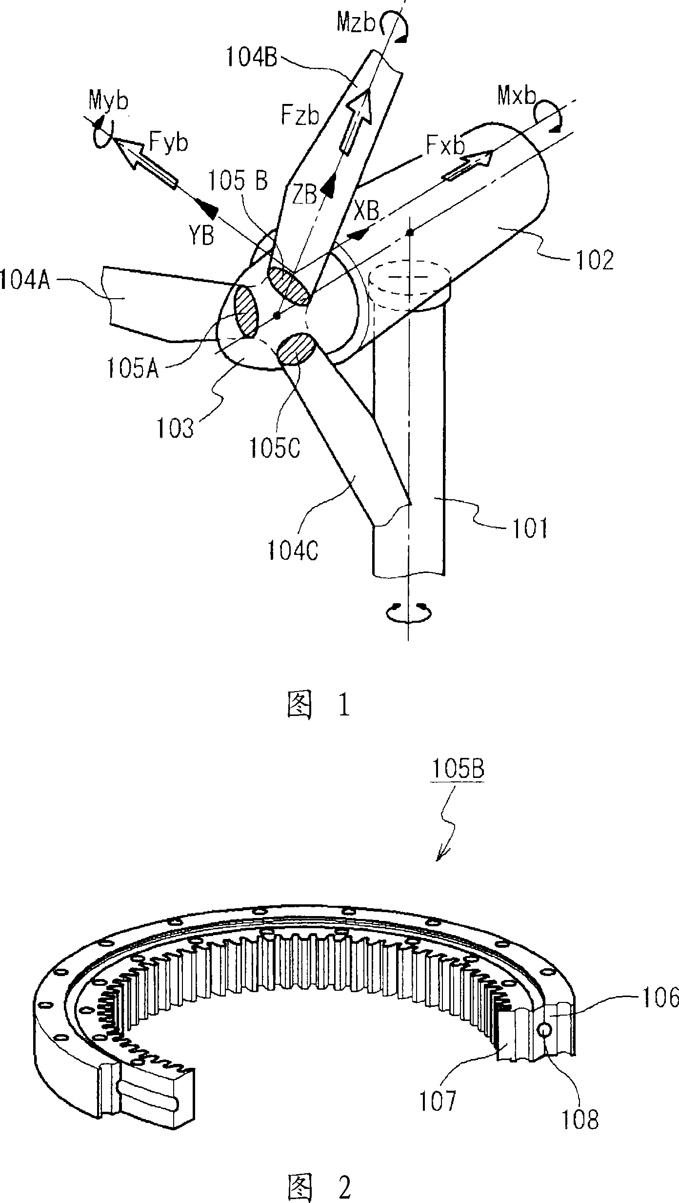
technical field [0001] The invention relates to a rotating ring bearing structure, in particular to a double row rotating ring bearing structure. Background technique [0002] In order to protect the global environment, it is desired to use natural energy that is less burdensome to the environment. As a natural energy source, wind energy has a promising future. A windmill generator is a rotating machine that converts wind energy into electricity. As shown in FIG. 1 , the wind turbine generator includes a support tower, a wind turbine base 102 rotatably supported by the support tower, and an impeller base (rotor head) 103 rotatably supported by the wind turbine base 102 . A plurality of wings (three wings in this example) 104A, 104B, 104C are rotatably supported (the pitch can be freely changed) by the rotor head 103 via rotating ring bearings 105A, 105B, 105C, respectively. As shown in FIG. 2 , the rotating ring bearing 105B is formed by a non-rotating outer ring 106 on t...

Claims


Application Information

Patent Timeline
IPC IPC(8): F16C19/18F16C19/38F16C19/40F16C19/46F16C33/58
CPCF16C19/18Y02E10/723F16C41/02F16C2300/14F16C2360/31Y02E10/722F05B2260/79F03D11/0008F16C19/505F03D7/0224F05B2260/74F16C2229/00F03D80/70Y02E10/72F16C19/46F16C19/38F16C33/58
Inventor 吉田孝文田北胜彦三宅寿生柴田昌明中岛圭太
Owner MITSUBISHI HEAVY IND LTD
Learn More