


Quick Research
Generate reliable direction feasibility study reports for your R&D in just a few steps.

Technical Q&A
Discover and master advanced knowledge NOW. Basics, ideas, possibilities, all at once.

Find Solutions
As an expert in R&D theories, this can generate solutions to your technical problems instantly.

Evaluate Feasibility
Analyze your overall solution with one click, know your potential R&D risks in advance.

Monitor Landscape
Get weekly tech updates, stay abreast of the latest tech innovations and key insights.
Boiler
一种锅炉、水管的技术,应用在锅炉领域,能够解决脱落、翅片裂痕、不能有效利用扩大传热面等问题,达到高耐久性、低NOx化的效果
- Summary
- Abstract
- Description
- Claims
- Application Information
AI Technical Summary
Problems solved by technology
Method used
Image


Examples
no. 1 example
[0047] Next, a boiler according to a first embodiment of the present invention will be described with reference to the drawings.
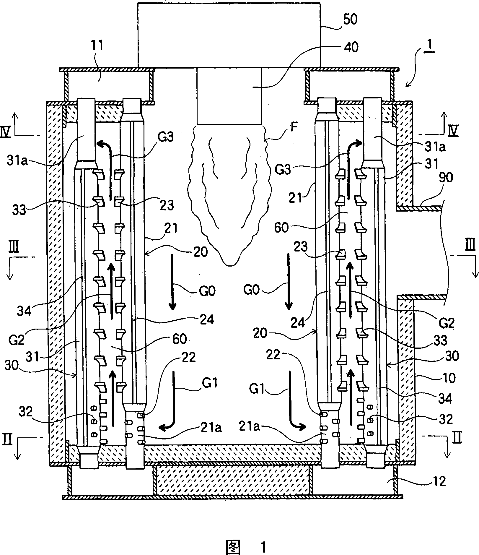
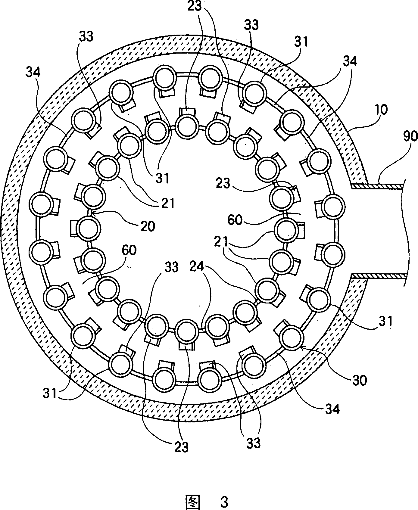
[0048] Fig. 1 is an explanatory diagram of a longitudinal section of a boiler according to a first embodiment of the present invention. Fig. 2 is a schematic explanatory diagram of a cross section taken along line II-II of Fig. 1 . Fig. 3 is a schematic explanatory diagram of a cross section taken along line III-III in Fig. 1 . Fig. 4 is a schematic explanatory view of a cross section taken along line IV-IV in Fig. 1 .
[0049] As shown in FIG. 1 etc., the boiler 1 of this embodiment is comprised using the tank body 10 which has the water tube group arranged in the ring, and the burner 40 arrange|positioned in the center part of these water tube groups. At a position above the combustor 40 , an air box 50 for supplying combustion air to the combustor 40 is provided.
[0050] The tank body 10 is constituted by erecting a plurality of water pipe g...
no. 2 example
[0072] Next, a boiler according to a second embodiment of the present invention will be described. The basic structure of the boiler of the second embodiment of the present invention is the same as that of the first embodiment described above. Therefore, in the following description, the same reference numerals as those of the first embodiment are assigned to the same parts as those of the first embodiment, and detailed description thereof will be omitted, and the configurations different from those of the first embodiment will be mainly described.
[0073] Fig. 5 is a schematic explanatory diagram of a cross section of a boiler according to a second embodiment of the present invention. More specifically, FIG. 5 is a schematic explanatory diagram corresponding to FIG. 2 of the first embodiment described above. That is, this FIG. 5 is a schematic explanatory diagram of a cross section near the inner gas flow path 25 (corresponding to the "gas flow path" of the present inventio...
no. 3 example
[0081] Next, a boiler according to a third embodiment of the present invention will be described. The basic structure of the boiler of the third embodiment of the present invention is the same as that of the first embodiment described above. Therefore, in the following description, the same reference numerals as those of the first embodiment are assigned to the same parts as those of the first embodiment, and detailed description thereof will be omitted, and the configurations different from those of the first embodiment will be mainly described.
[0082] Fig. 6 is an explanatory diagram of a longitudinal section of a boiler according to a third embodiment of the present invention. Fig. 7 is a schematic explanatory diagram of a cross section taken along line VII-VII of Fig. 6 . FIG. 8 is a schematic explanatory diagram of a cross section taken along line VIII-VIII in FIG. 6 . Fig. 9 is a schematic explanatory diagram of a cross section taken along line IX-IX of Fig. 6 .
[...
PUM
 Abstract
Description
Claims
Application Information
 - R&D Engineer
- R&D Manager
- IP Professional
- Industry Leading Data Capabilities
- Powerful AI technology
- Patent DNA Extraction
Browse by: Latest US Patents, China's latest patents, Technical Efficacy Thesaurus, Application Domain, Technology Topic, Popular Technical Reports.
© 2024 PatSnap. All rights reserved.Legal|Privacy policy|Modern Slavery Act Transparency Statement|Sitemap|About US| Contact US: help@patsnap.com