Workpiece transfer apparatus, control method for workpiece transfer apparatus, and press line

A conveying device and conveying control technology, which is applied in the stamping production line field, can solve problems such as control quantity variation, workpiece drop, workpiece conveying device failure, etc., and achieve the effect of suppressing vibration and preventing falling off

Active Publication Date: 2008-05-28
IHI CORP
View PDF1 Cites 5 Cited by
  • Summary
  • Abstract
  • Description
  • Claims
  • Application Information

AI Technical Summary

Problems solved by technology

[0006] However, in the above-mentioned prior art, there is a problem that the control amount input to the workpiece conveying device fluctuates drastically at the boundary between the mold interference zone and the conveying zone.
This fluctuation causes the vibration of the workpiece conveying device, resulting in the drop of the workpiece or failure of the workpiece conveying device.
In addition, in order to suppress the vibration of the workpiece conveying device, it is conceivable to increase the mechanical rigidity of the workpiece conveying device, but since the rigidity increases, the weight of the movable part increases, so the energy consumed for operating the workpiece conveying device increases, and there is a problem. The problem that the device cost also increases

Method used


Image

  • Workpiece transfer apparatus, control method for workpiece transfer apparatus, and press line
  • Workpiece transfer apparatus, control method for workpiece transfer apparatus, and press line
  • Workpiece transfer apparatus, control method for workpiece transfer apparatus, and press line

Examples


no. 1 Embodiment approach

[0033] Hereinafter, a first embodiment of the present invention will be described with reference to the drawings.

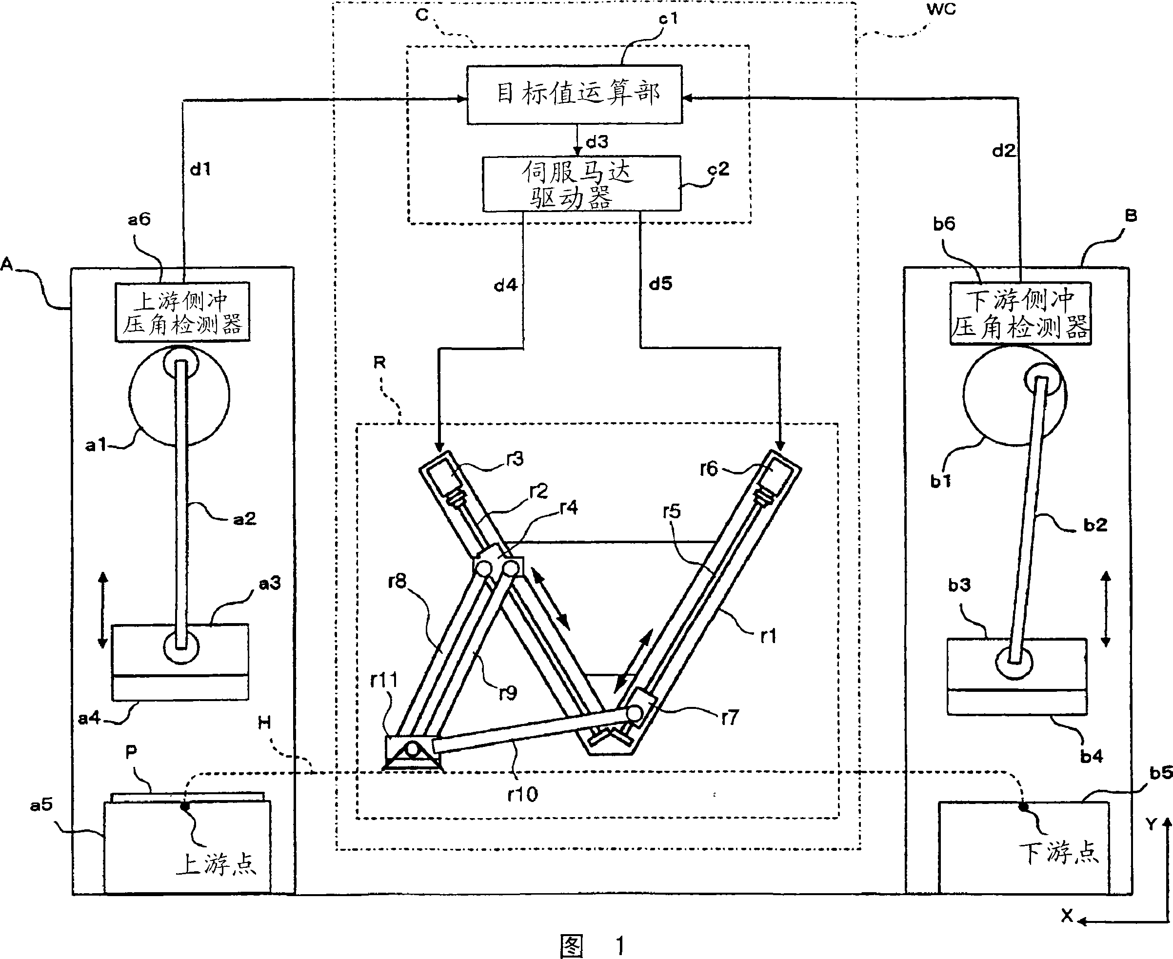
[0034] FIG. 1 is a schematic diagram showing the configuration of a tandem press line having a phase difference control method of a workpiece conveyance device according to the first embodiment. In the figure, reference numeral A is an upstream press device, B is a downstream press device, WC is a workpiece conveying device, and P is a workpiece. Moreover, the workpiece|work conveyance apparatus WC is provided with the control part C which has the target value calculation part c1 and the servomotor driver c2, and the workpiece|work conveyance part R. In addition, in FIG. 1 , the feed (feed-out) direction of the workpiece P is defined as the X-axis, and the vertical (vertical) direction is defined as the Y-axis.

[0035]As shown in FIG. 1 , the upstream side press device A and the downstream side press device B are separated from each other with a workpiece conve...

no. 2 Embodiment approach

[0069] Next, a second embodiment of the present invention will be described. In this second embodiment, another method for calculating the target transport position will be described. In addition, since the device configuration of the second embodiment is the same as that of the first embodiment, description thereof will be omitted, and the operation of the object computing unit c1 will be mainly described below.

[0070] FIG. 6 is an operation flowchart of the target value calculation unit c1 in the second embodiment. First, as in the first embodiment, the target value calculation unit c1 obtains the upstream press angle θu from the upstream press angle detector a5, and also obtains the downstream press angle θd from the downstream press angle detector b6 (step S10).

[0071] Next, the target value computing unit c1 obtains the first coordinates (Xu, Yu)={ Fx(θu), Fy(θu)}, and by substituting the downstream side stamping angle θd+planned phase difference Δθp for the upstream...


PUM


Abstract

The present invention provides a workpiece conveying device that uses a predetermined gripping mechanism to hold and convey the workpiece between punching devices that drive molds respectively, and has a conveying control mechanism that is based on a combination of punches located upstream in the conveying direction of the workpiece. The position of the above-mentioned gripping mechanism is controlled by a combined target value obtained by combining the die position of the device, that is, the position of the upstream side die, and the position of the die of the punching device on the downstream side, that is, the position of the downstream side die. The gripping mechanism moves smoothly, thereby suppressing the vibration of the workpiece conveying device in the press line.

Description

technical field [0001] The invention relates to a workpiece conveying device, a control method of the workpiece conveying device and a stamping production line. [0002] this application claims priority based on Japanese Patent Application No. 2005-165775 for which it applied in Japan on June 6, 2005, and uses the content here. Background technique [0003] Conventionally, a phase difference control method is known as a method of controlling a press device and a workpiece conveyance device in a tandem press line. In this phase difference control method, the punching angle, which is the die position of the upstream punching device, and the punching angle of the downstream punching device are controlled so that there is a predetermined phase difference so that the workpiece conveying device does not interfere with the die when loading / feeding workpieces. . According to such a phase difference control method, the workpiece can be conveyed without stopping the upstream press d...

Claims


Application Information

Patent Timeline
Patent Type & Authority Applications(China)
IPC IPC(8): B21D43/05
CPCB21D43/05B30B15/00B30B15/14B30B15/30
Inventor 高桥毅坂野肇山崎秀作
Owner IHI CORP
Why Eureka
Try Eureka