
A device and scanning method based on LED array scanning pattern

A technology of light-emitting diodes and scanning patterns, applied in lighting devices, cathode ray tube indicators, light sources, etc., can solve problems such as high cost and complex circuit structure

Inactive Publication Date: 2010-07-21
GENERALPLUS TECH INC +1
View PDF5 Cites 0 Cited by
  • Summary
  • Abstract
  • Description
  • Claims
  • Application Information

AI Technical Summary

Problems solved by technology

However, the graphic scanning unit of the prior art includes a driving circuit for LEDs, a control transistor and a capacitor, and the display unit also includes an AD converter, so there is a defect that the circuit structure is complex and the cost is relatively high.

Method used


Image

  • A device and scanning method based on LED array scanning pattern
  • A device and scanning method based on LED array scanning pattern
  • A device and scanning method based on LED array scanning pattern

Examples


Embodiment Construction

[0070] Specific embodiments of the present invention will be described in detail below in conjunction with the accompanying drawings.

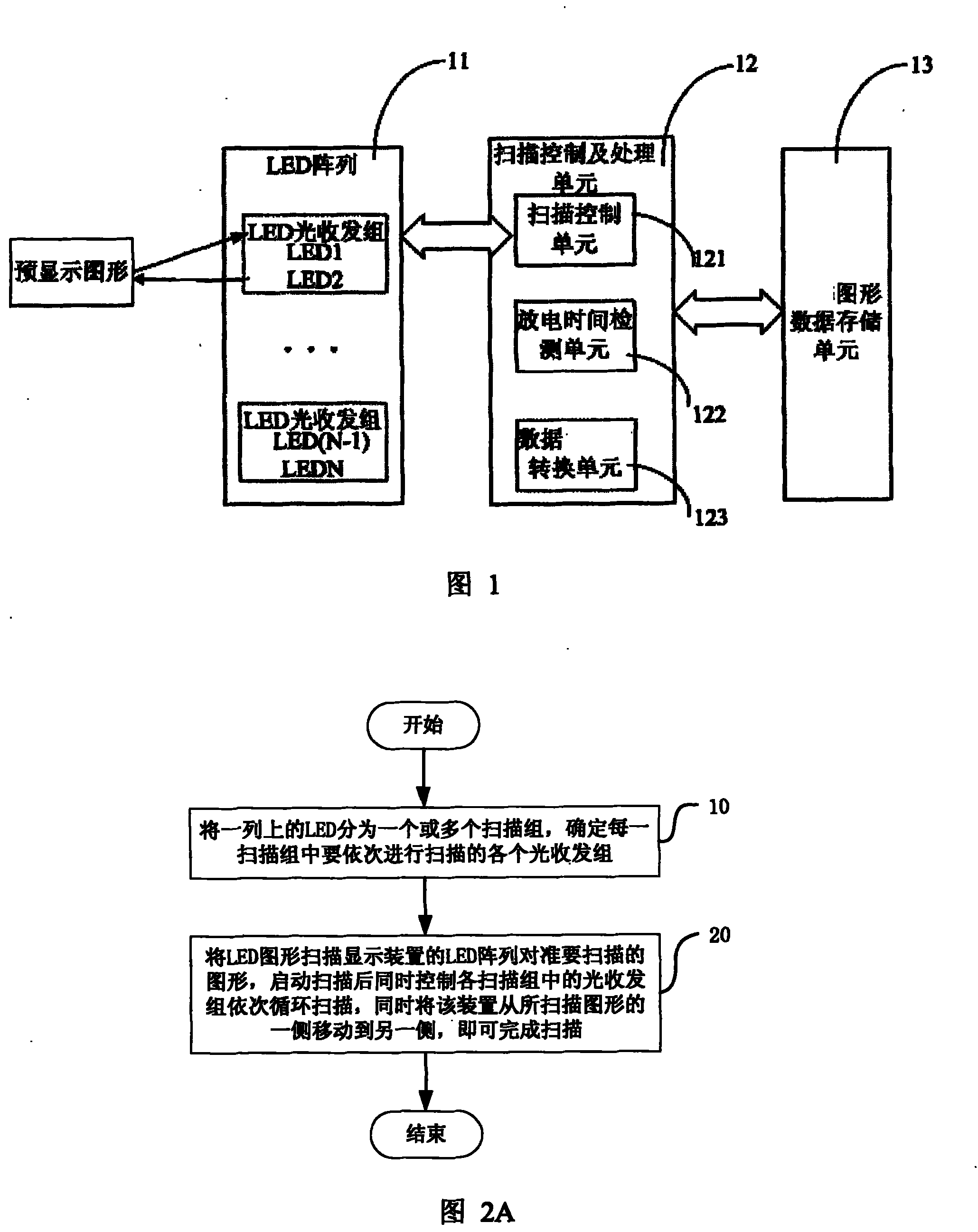
[0071] The LED graphics scanning display device includes a scanning processing part and a graphics display part. First, the graphics (also called images, patterns, etc.) to be displayed are scanned by the scanning processing part and the corresponding graphics data are recorded; when displaying, the graphics display part reads The recorded graphic data controls the LED to restore the scanned graphic.

[0072] FIG. 1 is a structural block diagram of the scanning processing part of this embodiment. As shown in the figure, the scanning processing part includes an LED array 11 , a scanning control and processing unit 12 and a graphic data storage unit 13 connected in sequence. in:

[0073] The LED array 11 includes at least a plurality of LEDs arranged in one column. In this embodiment, one column is used as an example for illustration. The "arra...


PUM


Abstract

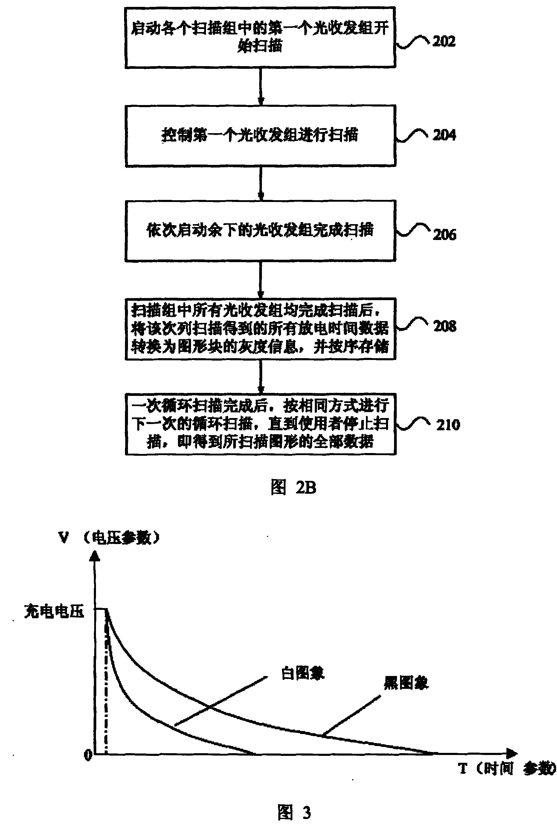
The invention discloses a device and method thereof, which can use the array of light-emitting diodes to scan graphics. The device comprises a LED array, a graphic data memory unit and a scanning control and processing unit which is connected with the LED array and the graphic data memory unit. The scanning control and processing unit can be used for controlling the light receiving and emitting group which consists of at least two LEDs on the LED array to scan graphics. In one scanning process of the light receiving and emitting group, one or more LED in the group, namely, receiving LED, can be charged firstly, and then the left one LED, namely an emitting LED, can be controlled to glow and to stop charging the receiving LED; and the discharging time of the receiving LEDs can be detected.After the discharging time detected in the scanning process is converted into the grayscale value of graphic blocks, and then the grayscale value of graphic blocks is stored in the graphic data memory unit. With simple circuit and low cost, the invention can realize the scanning and storing of graphics.

Description

technical field [0001] The present invention relates to a device including a light emitting diode (LED), and a method of scanning a pattern. Background technique [0002] In the PN junction of some semiconductor materials, when the injected minority carriers recombine with the majority carriers, the excess energy will be released in the form of light, thereby directly converting electrical energy into light energy. When a reverse voltage is applied to the PN junction, it is difficult for minority carriers to inject, so it does not emit light. This kind of diode made by the principle of injection electroluminescence is called light-emitting diode, or LED for short. [0003] In recent years, the application market of light-emitting diodes (LEDs) has developed rapidly, and its application fields have continued to expand. One of the applications is the LED graphic display part, such as a digital rocking stick or an LED shaking stick, which is a display device that is arranged ...

Claims


Application Information

Patent Timeline
Patent Type & Authority Patents(China)
IPC IPC(8): G09G3/32G09G5/36G09G3/00H05B37/02
CPCY02B20/42Y02B20/40
Inventor 罗立声杨柳
Owner GENERALPLUS TECH INC
Learn More