Projection optical system and projection image display
一种投影光学系统、光学系统的技术,应用在投影光学系统和投影图像显示装置领域,能够解决不能同时减小深度等问题,达到低失真、高分辨率、稳定光学性能的效果
- Summary
- Abstract
- Description
- Claims
- Application Information
AI Technical Summary
Problems solved by technology
Method used
Image
Examples
no. 1 example
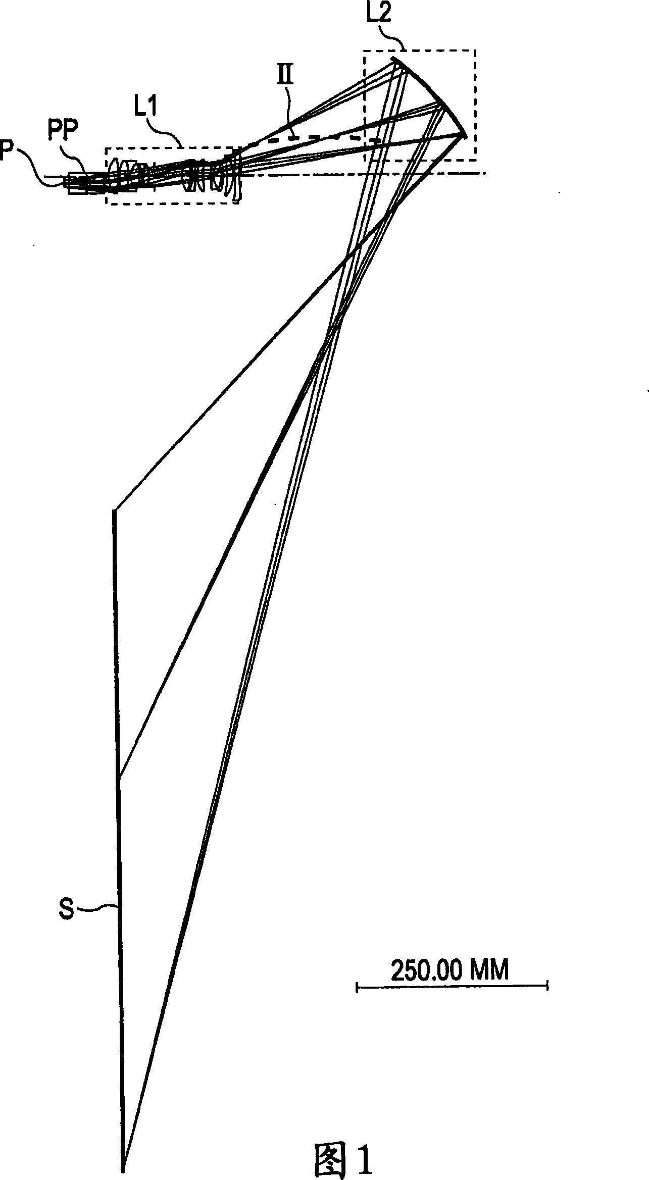
[0192] Fig. 1 illustrates an optical path according to a first embodiment. The image display element P functions as a modulation unit. Light emitted from a light source (not shown) is modulated by the image display element P according to a video signal. In this way, a primary imaging plane is formed. A reflective or transmissive dot-matrix liquid crystal display panel or a digital micromirror device (DMD) may be used for the image display element P. Referring to FIG. Reference numeral PP denotes a polarizing beam splitter (PBS), a color combining prism combining video signals of red, green and blue, or a total internal reflection (TIR) prism.
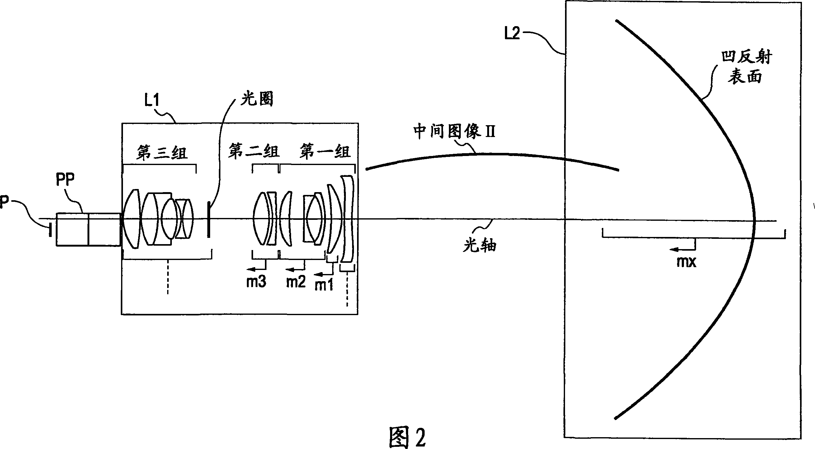
[0193] FIG. 2 illustrates a portion of the projection optical system shown in FIG. 1 in detail. The first optical system L1 includes a first group with negative refractive power, a second group with positive refractive power, a diaphragm, and a third group with positive refractive power in the following order from the secondary ima...
no. 2 example
[0216] Fig. 12 illustrates an optical path according to the second embodiment. The image display element P functions as a modulation unit. Light emitted from a light source (not shown) is modulated by the image display element P according to a video signal. In this way, a primary imaging plane is formed. For the image display element P, a reflective or transmissive dot-matrix liquid crystal display panel or a digital micromirror device (DMD) may be used. Reference numeral PP denotes a polarizing beam splitter (PBS), a color combining prism combining video signals of red, green and blue, or a total internal reflection (TIR) prism.
[0217] FIG. 13 illustrates a portion of the projection optical system shown in FIG. 12 in detail. The first optical system L1 includes a first group with negative refractive power, a second group with positive refractive power, a diaphragm, and a third group with positive refractive power in the following order from the secondary imaging plane ...
no. 3 example
[0238] Fig. 20 illustrates an optical path according to the third embodiment. The image display element P functions as a modulation unit. Light emitted from a light source (not shown) is modulated by the image display element P according to a video signal. In this way, a primary imaging plane is formed. For the image display element P, a reflective or transmissive dot-matrix liquid crystal display panel or a digital micromirror device (DMD) may be used. Reference numeral PP denotes a polarizing beam splitter (PBS), a color combining prism combining video signals of red, green and blue, or a total internal reflection (TIR) prism.
[0239] FIG. 21 illustrates a portion of the projection optical system shown in FIG. 20 in detail. The first optical system L1 includes a first group with negative refractive power, a second group with positive refractive power, a diaphragm, and a third group with positive refractive power in the following order from the secondary imaging plane s...
PUM
 Abstract
Description
Claims
Application Information
 - R&D
- Intellectual Property
- Life Sciences
- Materials
- Tech Scout
- Unparalleled Data Quality
- Higher Quality Content
- 60% Fewer Hallucinations
Browse by: Latest US Patents, China's latest patents, Technical Efficacy Thesaurus, Application Domain, Technology Topic, Popular Technical Reports.
© 2025 PatSnap. All rights reserved.Legal|Privacy policy|Modern Slavery Act Transparency Statement|Sitemap|About US| Contact US: help@patsnap.com


