Gear shaping machine and method for manufacturing or processing gear wheel

A gear shaping machine, a technology of processing direction, applied in the direction of manufacturing tools, gear tooth manufacturing devices, gear cutting machines, etc., to achieve the effect of good precision

Inactive Publication Date:
View PDF2 Cites 10 Cited by
  • Summary
  • Abstract
  • Description
  • Claims
  • Application Information

AI Technical Summary

Problems solved by technology

However, since the tool path in the known gear shaping machine is still determined by the cam shape, it is al...

Method used


Image

  • Gear shaping machine and method for manufacturing or processing gear wheel

Examples


Embodiment Construction

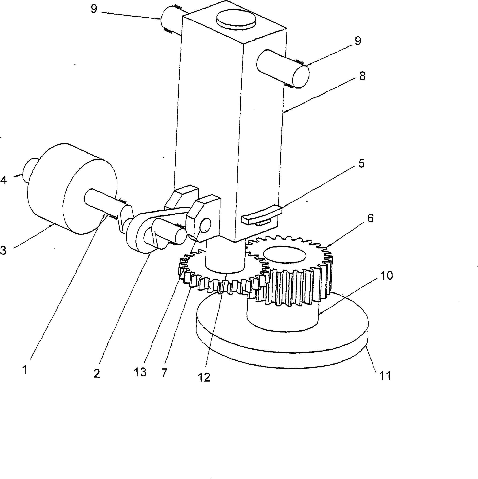
[0022] The embodiment of the gear shaping machine according to the invention has a tool 7 which is rigidly connected to a machining spindle 12 . The machining spindle 12 is in turn hydrostatically supported in the machining head 8 . Due to the reciprocating stroke movement of the machining spindle 12 , the tool 7 traverses the workpiece 6 in a reciprocating manner. The workpiece 6 is clamped on a table 11 by means of a clamp 10 . During this process, the machining spindle 12 as well as the tool 7 and the workpiece 6 are simultaneously rotated about their longitudinal axes in a geared manner. During the stroke movement, the machining head 8 , which holds the tool 7 via the machining spindle 12 , is rotatably supported on the support point 9 about an axis extending transversely to the machining direction, in order to advance the tool 7 to the workpiece 6 during the stroke movement. and exit from workpiece 6. A movement of the tool 7 transversely to the machining direction is ...


PUM


Abstract

The invention provides a gear shaping machine for manufacturing or processing gears. The machine comprises a cutter (7) and a processing head (8) for clamping the cutter, wherein, the processing head can cross traverse in the direction of processing to cause the cutter feeding or withdrawing relative to a workpiece. For the reason a direct drive device (3) is arranged, and the direct drive device drives the processing head to cross traverse in the direction of processing. The invention also relates a corresponding method for the manufacture or machining of gears, wherein, the processing head can cross traverse in the direction of processing to cause the cutter feeding or withdrawing relative to a workpiece by the direct drive device.

Description

technical field [0001] The invention relates to a gear shaping machine for manufacturing or machining gears, which comprises a tool and a machining head for holding the tool, wherein the machining head can move transversely along the machining direction, so that the tool can be moved in and out relative to the workpiece. The invention also relates to a corresponding gear manufacturing or finishing method. Background technique [0002] In such a gear shaping machine, the machining device performs a reciprocating stroke movement across the workpiece, as a result, a tooth profile is produced corresponding to the shape of the tool and the path of the tool through the workpiece. Here, the tool and the workpiece rotate around their axes in a gear mesh. In order to prevent the tool from rubbing against the workpiece in the reverse stroke, the tool retracts in the reverse stroke of the stroke movement cycle and enters the tool again in the processing stroke. For this reason, the pr...

Claims


Application Information

Patent Timeline
IPC IPC(8): B23F5/12B23F5/16B23F23/12
CPCB23F5/16B23F23/1218Y10T409/100159Y10T409/104452Y10T409/105088
Inventor G·哈斯
Why Eureka
Try Eureka