
Florescent lamp manufacturing installation and outer electrode manufacturing method using the same

An external electrode and manufacturing method technology, applied in the field of external electrode manufacturing and fluorescent lamp manufacturing device, can solve the problems of reducing work efficiency, reducing brazing quality, uneven coating, etc., to prevent cold welding phenomenon, improve brazing quality, Simple process effect

Inactive Publication Date: 2010-08-11
WEIHAI DMS OPTICAL ELECTROMECHANICAL CO LTD
View PDF1 Cites 0 Cited by
  • Summary
  • Abstract
  • Description
  • Claims
  • Application Information

AI Technical Summary

Problems solved by technology

[0012] First of all, the solder liquid cannot completely penetrate into the tiny gap between the fluorescent lamp and the metal tube, so it is difficult to obtain satisfactory diffusion and penetration in the dipping operation
[0013] As mentioned above, if the diffusion and penetration of the solder liquid between the contact surface of the fluorescent lamp and the metal tube is reduced, not only an uneven coating will be formed between the contact surfaces, but also tiny voids will be generated on the coating, thereby reducing the quality of brazing
[0014] In addition, in order to improve the diffusion of the solder liquid, only the solder liquid is heated inside the container (above 300 degrees Celsius), which will cause a large temperature deviation between the solder liquid and the base material (fluorescent lamps and metal tubes) during the dipping operation. Therefore, it is difficult to improve the diffusion and penetration of solder liquid
[0015] Moreover, it is difficult to fundamentally improve the diffusion and penetration of the solder liquid only by putting the metal tube on the end of the glass tube in the first capping process and dipping it in this state.
[0016] Therefore, in the aforementioned Patent Publication No. 10-2005-0090519 - External Electrode Forming Method for External Electrode Fluorescent Lamp, it is difficult to improve the brazing quality during the dipping operation, and too many defective products will be produced, so that not only the working efficiency is reduced, but also it is difficult to Formation of external electrodes with excellent electrical conduction performance

Method used


Image

  • Florescent lamp manufacturing installation and outer electrode manufacturing method using the same
  • Florescent lamp manufacturing installation and outer electrode manufacturing method using the same
  • Florescent lamp manufacturing installation and outer electrode manufacturing method using the same

Examples


Embodiment Construction

[0050] Hereinafter, preferred embodiments of the present invention will be described in detail with reference to the accompanying drawings, and will be described within the scope that those skilled in the art can practice the present invention.

[0051] Also, the present invention can be carried out in various ways, and therefore the scope of claims of the present invention is not limited to the following examples.

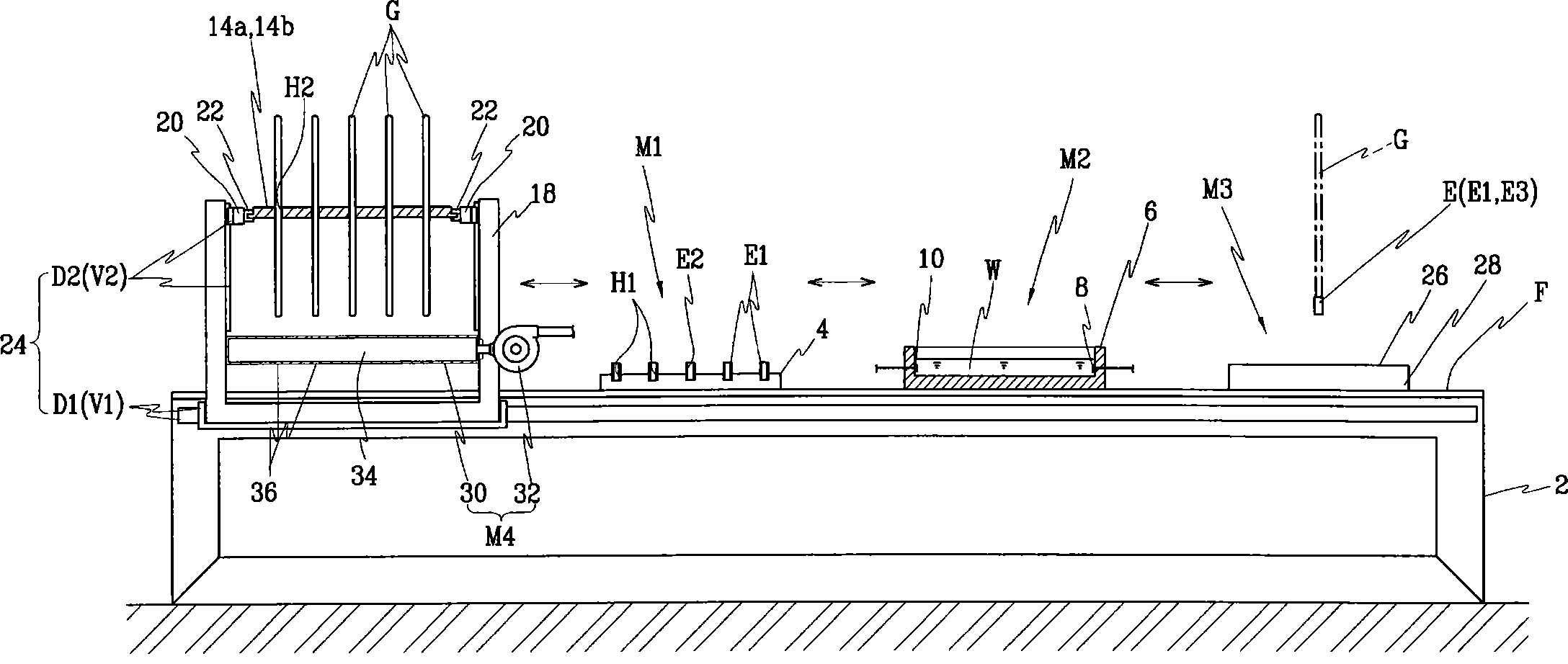
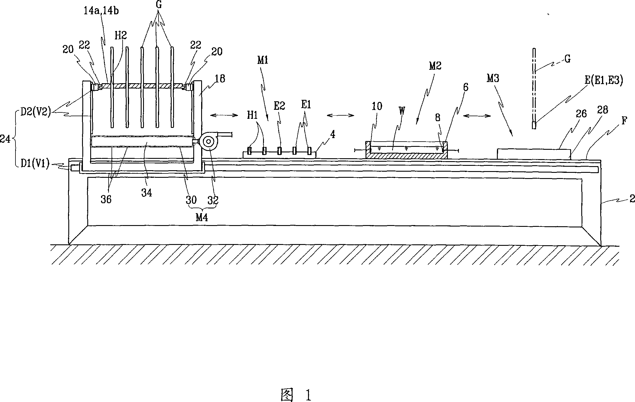
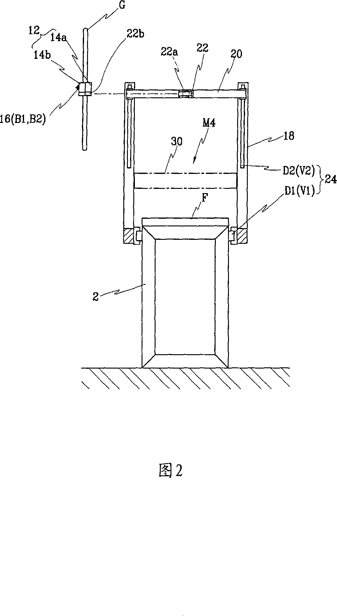
[0052] 1 and 2 are schematic diagrams of the overall structure of a fluorescent lamp manufacturing device according to an embodiment of the present invention, and symbol 2 denotes a workbench.

[0053] The workbench 2 can use a conventional four-corner support with a flat work surface F on it, and when the work surface F is based on FIG. 1 , it can provide a work area that is lengthened toward the left and right.

[0054] In addition, a capping device M1 and a dipping device M2 are installed on the table 2, and are used for forming the external electrodes E on a p...


PUM


Abstract

The invention relates to a fluorescent lamp producing device, in particular to a fluorescent lamp producing device which forms an outer electrode easily and greatly increases the braze welding quality of the outer electrode, as well as a method for producing the outer electrode through the device. The fluorescent lamp producing device comprises a working table provided with a working surface; a glass-tube fixing device detachably fixing a plurality of fluorescent lamp glass-tubes on the working surface vertically; a driving device for moving the glass-tube fixing device towards to more than two directions along the working surface; a cap-adding device arranged on the working surface and provided with a pallet having a plurality of electrode caps and used for adding the electrode caps on the two ends of the fluorescent lamp glass-tube; a pre-heating device for heating the end of the fluorescent lamp glass-tube, which is added with the electrode cap through a heating component; a dipping device provided with a dipping tank for holding welding-material liquids and used for braze-welding the cap-added end of the fluorescent lamp glass-tube inside the welding-material liquids.

Description

technical field [0001] The present invention relates to a fluorescent lamp manufacturing device and an external electrode manufacturing method using the device, in particular to a method for easily forming the external electrode of the external electrode fluorescent lamp by moving the glass tube for the fluorescent lamp in an in-line manner. A quality fluorescent lamp manufacturing device and an external electrode manufacturing method using the device. Background technique [0002] Generally, a liquid crystal display device has a backlight module for providing light to a light-receiving element-a liquid crystal display panel, and the backlight module includes a fluorescent lamp, a light guide plate, a reflector plate, and an optical lens. [0003] The fluorescent lamps used for backlighting can be roughly classified into cold cathode fluorescent lamps and external electrode fluorescent lamps according to the position of electrodes. [0004] Among the above-mentioned two typ...

Claims


Application Information

Patent Timeline
Patent Type & Authority Patents(China)
IPC IPC(8): H01J9/02
CPCH01J9/02H01J9/20H01J9/247H01J65/00
Inventor 金成海金圣中全范洙
Owner WEIHAI DMS OPTICAL ELECTROMECHANICAL CO LTD
Learn More