
Cleaning apparatus for discharge nozzle

A technology for cleaning devices and nozzles, applied in the direction of spraying devices, etc., can solve problems such as high cost, high operating cost, and large-scale devices, and achieve the effects of reducing equipment costs, reducing operating costs, and reducing consumption

Active Publication Date: 2008-05-21
CHUGAI RO CO LTD
View PDF3 Cites 10 Cited by
  • Summary
  • Abstract
  • Description
  • Claims
  • Application Information

AI Technical Summary

Problems solved by technology

In the state where the concentration of the coating liquid present at the tip of the nozzle has risen, once the next coating operation is performed, there is a problem that the object to be coated will be streaked due to the high-concentration coating liquid. The phenomenon of uneven coating, or the phenomenon of film cracking
[0010] However, in such a cleaning device, many devices are required to sufficiently remove the coating liquid supplied to the outer peripheral surface of the rotating roller, and there are problems of high cost and large size of the device, and in this case, there are also problems as follows: As mentioned above, in order to always spray new cleaning liquid from the new liquid spray nozzle to the outer peripheral surface of the rotating roller, a large amount of cleaning liquid is required, the operation cost is high, and the cleaning liquid needs to be treated after cleaning.

Method used


Image

  • Cleaning apparatus for discharge nozzle
  • Cleaning apparatus for discharge nozzle
  • Cleaning apparatus for discharge nozzle

Examples


Embodiment Construction

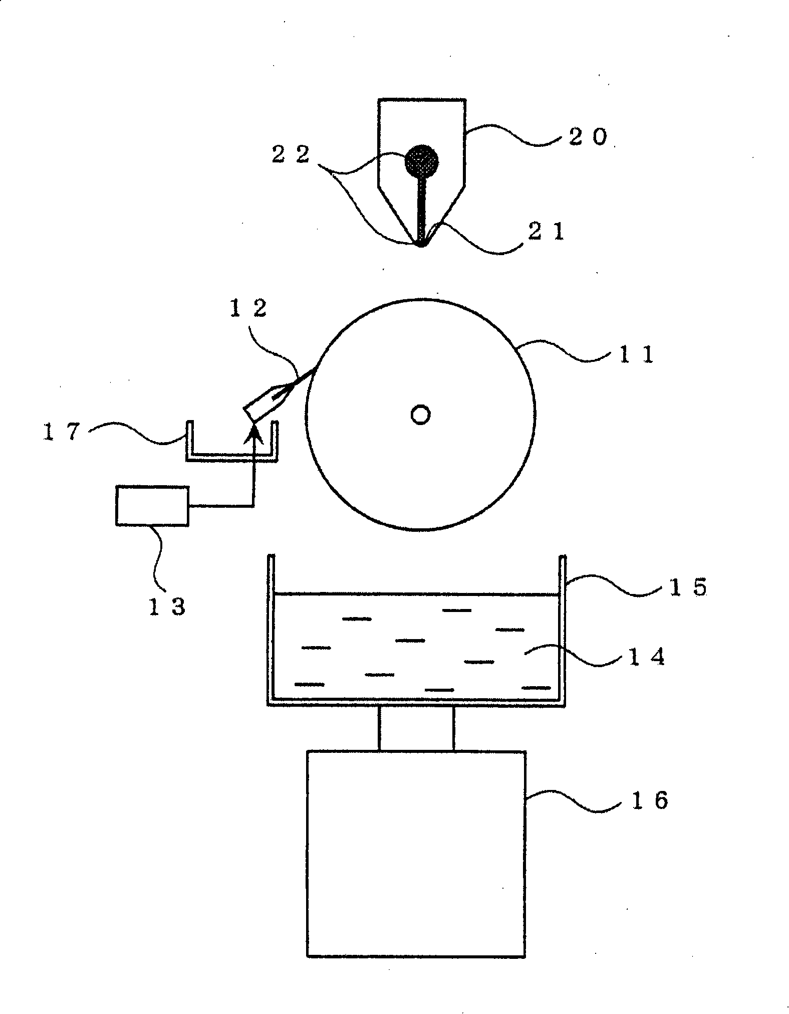
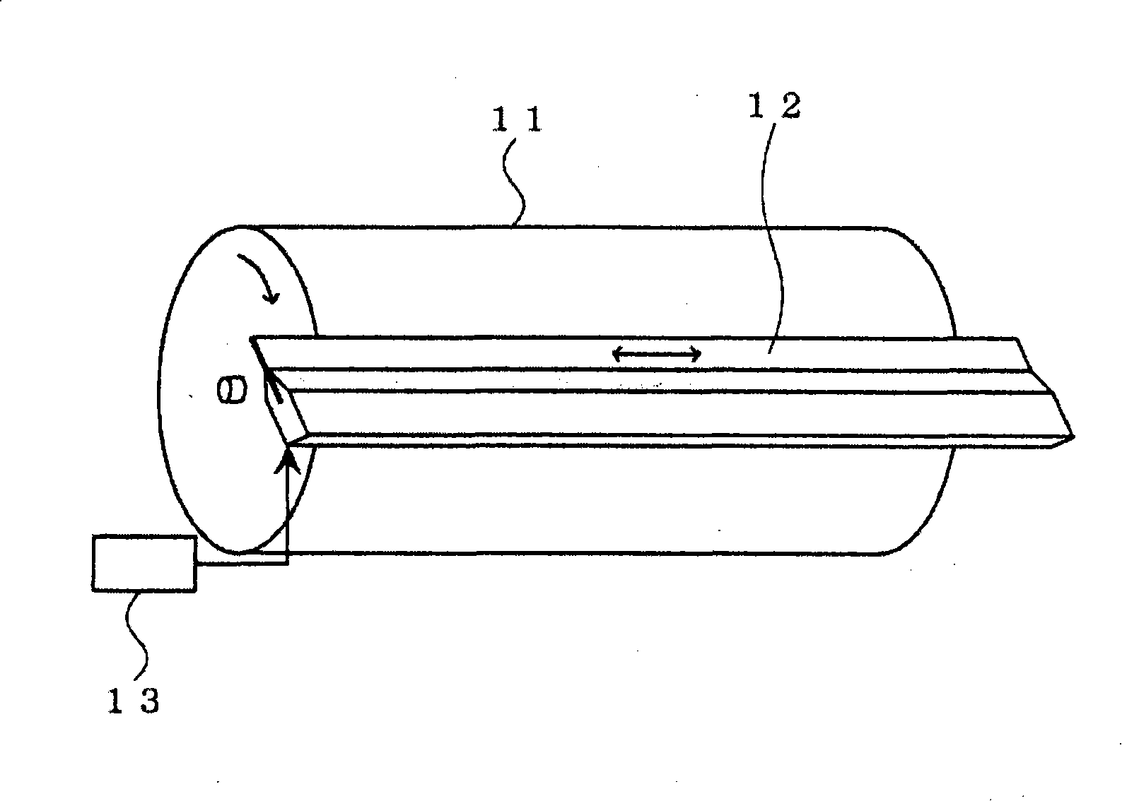
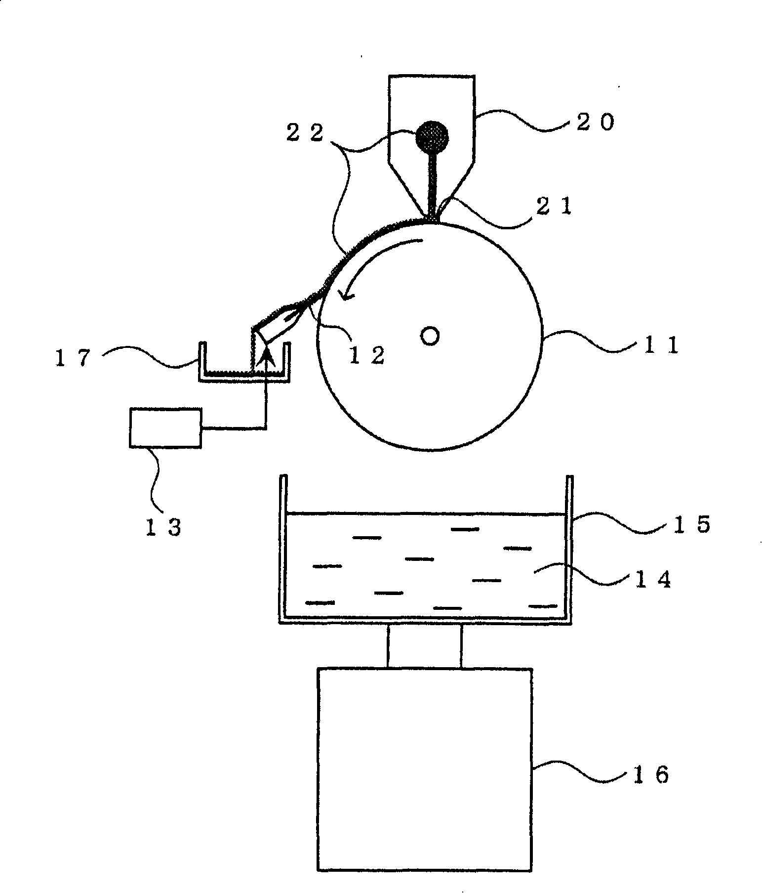
[0035] Next, a nozzle cleaning device according to a reference embodiment of the present invention will be described with reference to the drawings, and then a nozzle cleaning device according to an embodiment of the present invention which is further improved on the nozzle cleaning device according to this reference embodiment will be described in detail. The nozzle cleaning device of the present invention is not limited to the following embodiments, and can be appropriately modified and implemented without changing the gist of the invention.

[0036] Such as Figure 1 ~ Figure 4 As shown, in the nozzle cleaning device of the reference form, a scraper 12 whose front end is in contact with the outer peripheral surface of a rotating roller 11 that is rotationally driven by a rotating device (not shown) is provided. In the state where the outer peripheral surface of the figure 2 As shown, the scraper 12 can be reciprocated in the axial direction of the rotating roller 11 by us...


PUM


Abstract

An objective of the present invention is to efficiently remove dispensing liquid existing at front end of discharge nozzle by a simple equipment without using a large amount of washing liquid. A rotation roller 11 for holding dispensing liquid discharged from a slit-shaped discharge port 21 provided at a front end of a discharge nozzle 20 is such provided as not to contact the discharge nozzle. A blade 12 for removing the dispensing liquid held on a peripheral surface of the rotation roller is such provided as to be able to reciprocate in an axis direction of the rotation roller, while a washing brush 12b is such provided at a position in a downstream side of the rotation direction of the rotation roller with respect to the blade as to be able to reciprocate in the axis direction of the rotation roller while contacting the peripheral surface of the rotation roller together with the blade. A washing liquid-supplying apparatus 15 for supplying washing liquid 14 to the peripheral surface of the rotation roller is provided in the downstream side of the rotation direction of the rotation roller with respect to the washing brush. In a stage of removing the dispensing liquid from the rotation roller by the blade, the washing liquid is not supplied to the rotation roller, while on the other hand, at least in a stage of supplying the washing liquid to the peripheral surface of the rotation roller, the blade and the washing brush are made to reciprocate in the axis direction of the rotation roller.

Description

[0001] The present invention is an invention based on Japanese Patent Application No. 2006-308621, which claims priority. technical field [0002] The present invention relates to a nozzle cleaning device for cleaning a nozzle installed in a coating device for coating various coating liquids such as glass, resin film, metal foil, etc., and particularly relates to such a nozzle Cleaning device: After the coating liquid is supplied to the object to be coated from the slit-shaped discharge port provided at the front end of the nozzle for coating, the discharge port is provided during the period until the next coating. Clean the tip of the nozzle. Background technique [0003] Conventionally, when manufacturing plasma display panels, organic electroluminescence display panels, liquid crystal display panels, etc., coating liquids are applied to various substrates such as glass, resin films, and metal foils, respectively, by coating equipment. [0004] As such a coating device, a...

Claims


Application Information

Patent Timeline
Patent Type & Authority Applications(China)
IPC IPC(8): B05B15/02
CPCB05B15/50
Inventor 野尻大介甲田正纪黑木贵史
Owner CHUGAI RO CO LTD
Learn More