
High-volume hydraulic two-stage pressure-regulating distributor

A large flow, distributor technology, applied in the direction of fluid pressure actuators, servo motor components, mechanical equipment, etc.

Inactive Publication Date: 2008-05-14
HARBIN INST OF TECH
View PDF0 Cites 8 Cited by
  • Summary
  • Abstract
  • Description
  • Claims
  • Application Information

AI Technical Summary

Problems solved by technology

At present, there is no pressure-regulating distributor that can realize high and low pressure two-stage working pressure.

Method used


Image

  • High-volume hydraulic two-stage pressure-regulating distributor

Examples


Embodiment Construction

[0020] The present invention will be further described below in conjunction with accompanying drawing and specific embodiment:

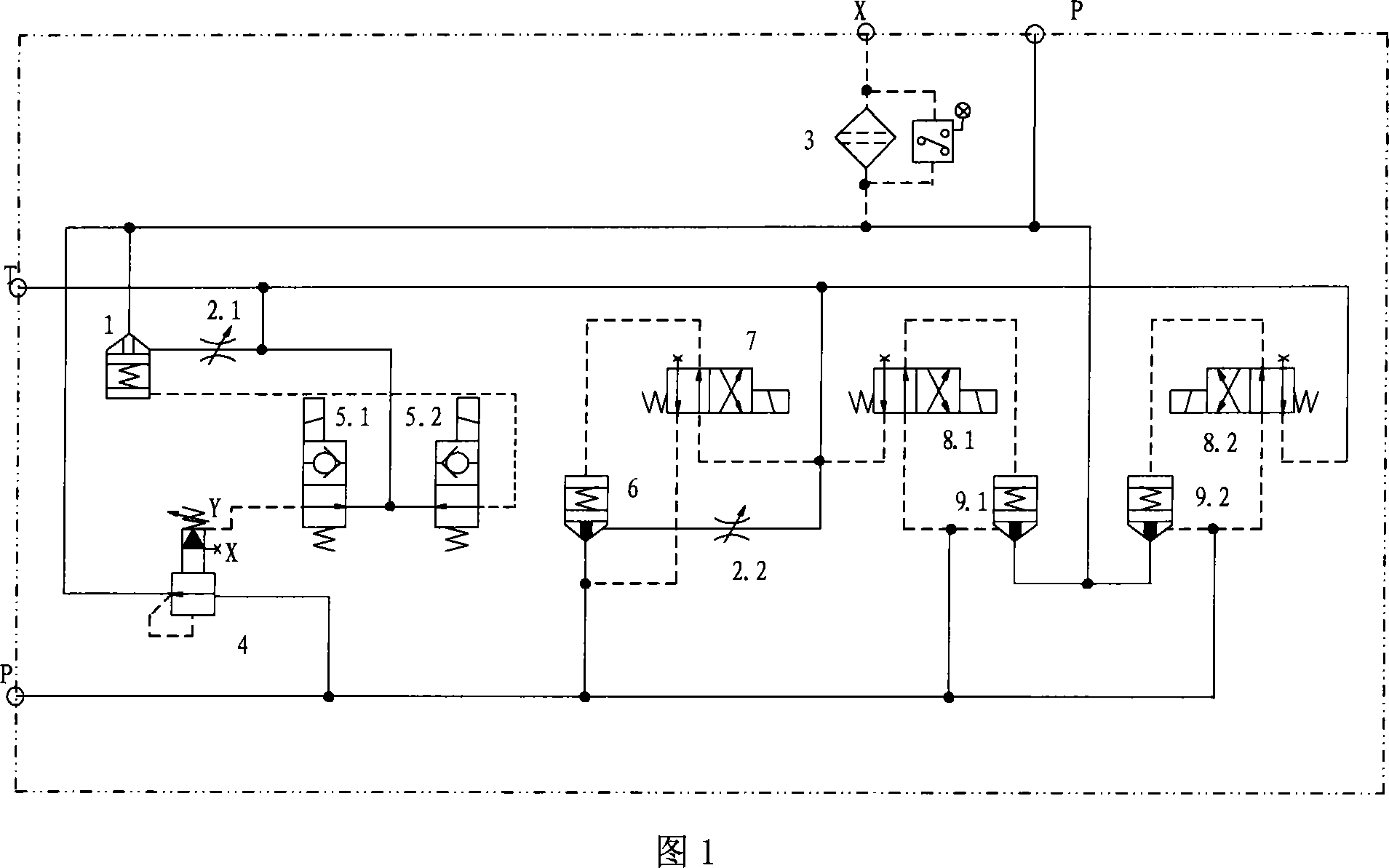
[0021] 1, this embodiment includes a low-pressure circuit, a high-pressure circuit, a hydraulic system interface and a fuel tank interface, the low-pressure circuit and the high-pressure circuit are respectively connected to the hydraulic system interface and the fuel tank interface, and the low-pressure circuit includes cartridge valves 1, 6, and an electromagnetic reversing valve 7 . Electromagnetic reversing valves 8.1, 8.2 are respectively connected to cartridge valves 9.1, 9.2, and an oil filter 3 is arranged at the interface of the hydraulic system. A throttle valve 2.1 and a throttle valve 2.2 are arranged on the low-pressure circuit. In this embodiment, by controlling the on-off control cartridge valves 9.1 and 9.2 of the electromagnetic reversing valves 8.1 and 8.2, respectively, the process of raising and lowering pressure from low pressur...


PUM


Abstract

The invention provides a large-flux hydraulic two-step pressure regulation distributor, comprising a low pressure loop, a high pressure loop, a hydraulic system interface, and an oil tank interface; the low pressure loop and the high pressure loop are respectively connected with the hydraulic system interface and the oil tank interface; the lower pressure loop comprises insertion valves 1, 6, electromagnetic conversion valves 7, 5.1, and 5.2 and a pressure reducing valve 4; the electromagnetic conversion valves 5.1 and 5.2 are respectively connected with the insertion valves 1 and the pressure reducing valve 4; the electromagnetic conversion valve 7 is connected with the insertion valve 6; the high pressure loop comprises insertion valves 9.1 and 9.2 and electromagnetic conversion valves 8.1 and 8.2; the electromagnetic conversion valves 8.1 and 8.2 are respectively connected with the insertion valves 9.1 and 9.2; the hydraulic system interface is provided with an oil filter 3. The invention has two-step high pressure and low pressure regulation function and pressure releasing function, which can implement the smooth shift between a high pressure and a low pressure.

Description

(1) Technical field [0001] The invention relates to hydraulic distributor technology, in particular to a large-flow hydraulic two-stage pressure-regulating distribution technology. (2) Background technology [0002] In hydraulic systems such as hydraulic vibration test rigs, hydraulic seismic test rigs and hydraulic road simulation test rigs, it is usually required that the hydraulic system can provide high and low pressure working pressures. The system starts normally at low pressure, and after the start, the hydraulic system smoothly switches from low pressure to working pressure (high pressure). And still do not have the pressure regulating distributor that can realize high and low pressure two grades of working pressures at present. (3) Contents of the invention [0003] The purpose of the present invention is to provide a large-flow hydraulic two-stage pressure-regulating distributor with high-low pressure two-stage pressure regulation function and pressure unloading...

Claims


Application Information

Patent Timeline
IPC IPC(8): F15B13/044
Inventor 韩俊伟叶正茂丛大成张辉
Owner HARBIN INST OF TECH
Learn More