Wave soldering bath

A welding bath and molten solder technology, which is used in welding equipment, tin feeding devices, electrical components, etc., can solve the problems of burns and charring of automatic brazing device wiring or workplace floors, and removal of labor and other problems.

Active Publication Date: 2008-05-07
SENJU METAL IND CO LTD
View PDF3 Cites 1 Cited by
  • Summary
  • Abstract
  • Description
  • Claims
  • Application Information

AI Technical Summary

Problems solved by technology

When the oxides are spilled from the wave soldering tank, there may be a problem of scorching the wiring of the automatic brazing equipment or the floor of the workplace, or splashing on the operator after spilling and causing burns
[0014] When a partition made of metal mesh or a porous plate is installed between the storage tank and the main body of the tank, it is true that the oxides can be filtered out through the partition without moving to the side of the jet pump, but the oxides will adhere to the partition. boards, resulting in laborious and dangerous removal

Method used


Image

  • Wave soldering bath
  • Wave soldering bath
  • Wave soldering bath

Examples


Embodiment Construction

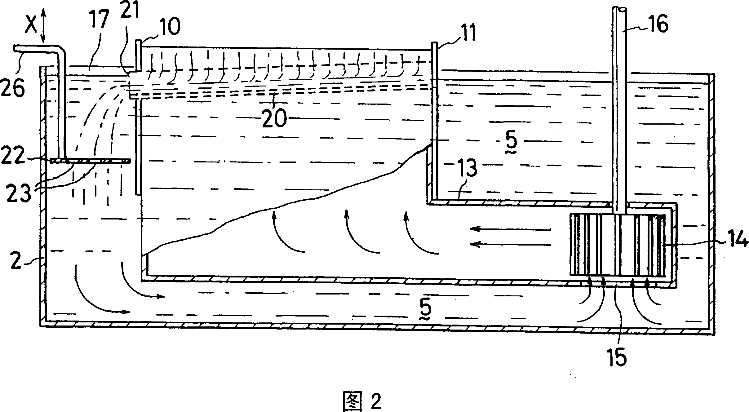
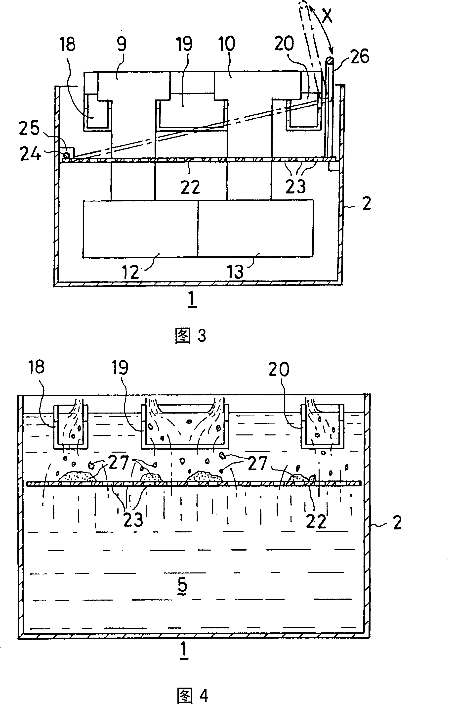
[0034]The installation position of the porous plate in the wave solder bath of the present invention, that is, the installation position from the liquid surface of molten solder is preferably 10 to 200 mm. When the distance between the installation position of the porous plate and the liquid surface of the molten solder is less than 10 mm, the molten solder flowing down from the groove is bounced by the porous plate to produce oxides, and the molten solder flowing down from the groove passes through the porous plate in a state of potential energy. The holes, together with the oxides, sink down and are sucked in by the jet pump. On the other hand, when the distance from the installation position of the perforated plate to the liquid surface is greater than 200 mm, the molten solder flowing down from the groove moves to the jet pump side before reaching the perforated plate, causing oxides to be sucked by the jet pump.

[0035] In addition, the hole diameter of the perforated pl...


PUM

PropertyMeasurementUnit
pore sizeaaaaaaaaaa

Abstract

In conventional wave soldering baths, oxides mixed in a molten solder are sucked through a suction port of duct into a duct, are emitted through a jet nozzle and stick to printed boards. There is provided a wave soldering bath comprising an oxide reservoir disposed on the side opposite to pump installation side and a conduit having its pump side dammed secured to the side face of jet nozzle. Further, the wave soldering bath has a porous plate with a multiplicity of holes provided through perforation rotatably mounted in the middle of the oxide reservoir.

Description

technical field [0001] The present invention relates to a wavy soldering tank which jets molten solder and makes the jetted molten solder contact with a printed board so that the solder adheres to the printed board. Background technique [0002] When soldering printed circuit boards incorporated into home appliances such as televisions and video recorders, a flow method suitable for mass production is generally used. The so-called flow method refers to a method of brazing by an automatic brazing device. The automatic soldering equipment used in the flow method is equipped with processing equipment such as a solder applicator, a preheater, a wave soldering tank, and a cooler, and a conveyor belt for transportation is installed on these processing equipment. When brazing the printed circuit board, the printed circuit board is transported and fixed on the processing device with a conveyor belt, and moves on it, and at the same time, the flux is applied by the solder applicator...

Claims


Application Information

Patent Timeline
Patent Type & Authority Applications(China)
IPC IPC(8): H05K3/34B23K1/08
CPCH05K3/3468B23K3/0653B23K1/08H05K3/34B23K3/06
Inventor 禅三津夫小泽聪
Owner SENJU METAL IND CO LTD
Why Eureka
Try Eureka