Reusable atomization type trachea cannula

A technology of endotracheal intubation and intubation, which is applied in the direction of endotracheal intubation, valves, and other medical devices. It can solve problems such as drug waste, patient discomfort, and drug solution accumulation and blockage, so as to improve practicability, increase practicability, Easy to clean effect

Inactive Publication Date: 2020-07-03
潘龙飞
View PDF0 Cites 0 Cited by
  • Summary
  • Abstract
  • Description
  • Claims
  • Application Information

AI Technical Summary

Problems solved by technology

[0003] The existing tracheal intubation has some disadvantages: 1. The existing tracheal intubation equipment does not have an anti-backflow device. When the patient is intubated while adding medicinal liquid, it is easy to flow out from the other end of the intubation tube, resulting in a waste of medicinal liquid , reducing the practicality of the intubation
2. The existing tracheal intubation equipment is integrated, which is inconvenient to separate the main tube from the intubation tube, resulting in a waste of overall resources and reducing the practicability of the intubation tube
3. When adding liquid medicine to the existing tracheal intubation, part of the liquid medicine has a high concentration, which is inconvenient to flow into the patient's body from the intubation tube. tube usability
4. The existing intubation tube is inserted into the patient's throat, and there is a large gap between the outer wall of the intubation tube and the patient's throat, which shakes in the throat, causing severe discomfort to the patient, and affecting the effect of feeding the medicinal solution, reducing the risk of insertion. tube usability

Method used


Image

  • Reusable atomization type trachea cannula
  • Reusable atomization type trachea cannula
  • Reusable atomization type trachea cannula

Examples


Embodiment Construction

[0027] In order to make the purpose, technical solutions and advantages of the present invention clearer, the present invention will be further described in detail below in conjunction with the accompanying drawings. Obviously, the described embodiments are only some of the embodiments of the present invention, rather than all of them. Based on the embodiments of the present invention, all other embodiments obtained by persons of ordinary skill in the art without making creative efforts belong to the protection scope of the present invention.

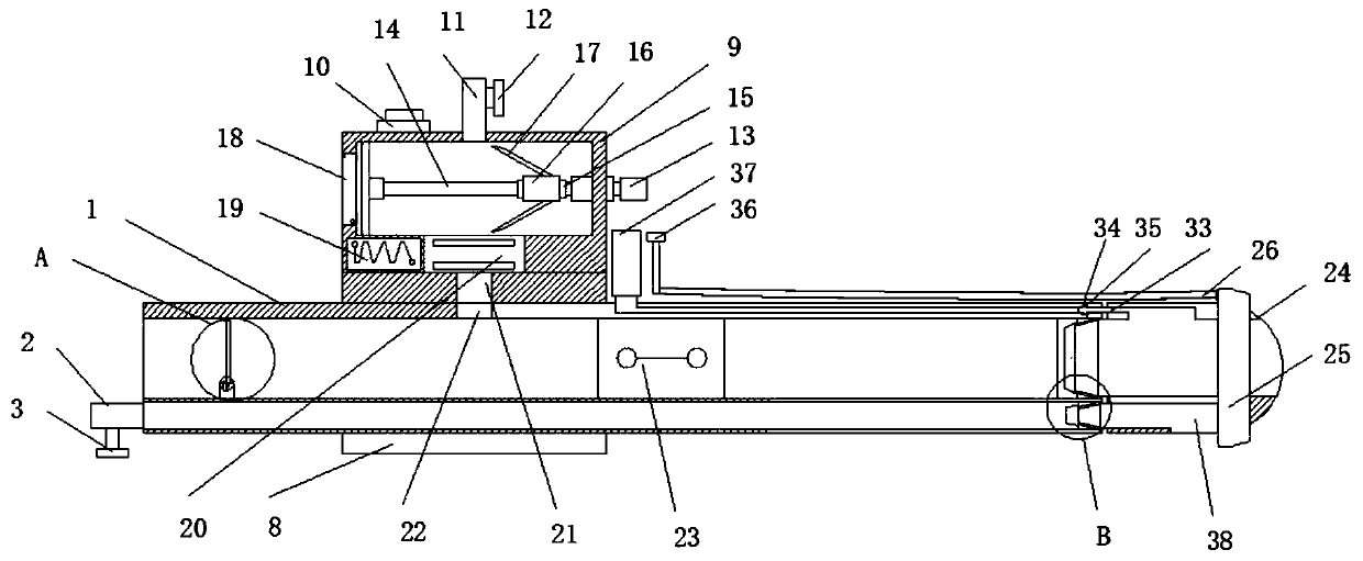
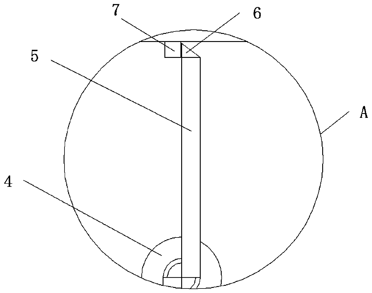
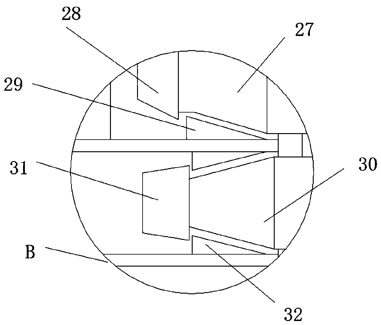
[0028] The following will combine Figure 1 ~ Figure 3 A reusable atomizing endotracheal intubation tube according to the embodiment of the present invention is described in detail.

[0029] refer to figure 1 , figure 2 with image 3 As shown, a reusable atomized endotracheal intubation tube provided by the embodiment of the present invention includes a tube body A1, a connecting tube A2 is fixedly connected to the outer wall of the...


PUM


Abstract

The invention discloses a reusable atomization type trachea cannula, and belongs to the field of medical treatment. The reusable atomization type trachea cannula comprises a cannula body A, wherein the outer wall of the lower end of the left side of the cannula body A is fixedly connected with a connecting tube A; a valve A sleeves the lower end of the connecting tube A; a rotating shaft is rotationally mounted on the inner wall of the lower side of the left side of the cannula body A; a rotating block is rotationally mounted at the upper end of the rotating shaft; a stop block is fixedly mounted on the outer side wall of the upper end of the rotating block; a fixed block is fixedly mounted on the inner wall of the upper end of the left side of the cannula body A; a mounting sleeve fixedlysleeves the outer wall of the center of the cannula body A; a box body is fixedly mounted at the upper end of the mounting sleeve; a control button is fixedly mounted on the outer wall of the left side of the upper end of the box body; and a liquid inlet pipe is fixedly mounted on the outer wall of the upper end of the center of the box body. By arranging a rotating structure, an anti-backflow device and a structure convenient to mount and dismount are mounted, and the practicability of the cannula is improved.

Description

technical field [0001] The invention relates to the technical field of tracheal intubation, in particular to a reusable atomized tracheal intubation tube. Background technique [0002] Endotracheal intubation refers to the technique of inserting a special endotracheal tube into the trachea through the glottis, which is called endotracheal intubation. This technique can provide the best conditions for airway patency, ventilation and oxygen supply, respiratory tract suction and prevention of aspiration. , Emergency tracheal intubation technology has become an important measure in the process of cardiopulmonary resuscitation and rescue of critically ill patients with respiratory dysfunction. Endotracheal intubation is an important rescue technique commonly used in emergency work. It is one of the most widely used, most effective and fastest means in respiratory management, and plays a vital role in saving patients' lives and reducing the mortality rate. [0003] The existing t...

Claims


Application Information

Patent Timeline
IPC IPC(8): A61M16/04A61M39/22A61M39/24
CPCA61M16/0402A61M16/0434A61M16/0463A61M16/0486A61M16/0497A61M39/223A61M39/24
Inventor 潘龙飞任松
Owner 潘龙飞
Why Eureka
Try Eureka