Power supply circuit and control circuit for use in the same
A power circuit and circuit technology, applied in the direction of electronic commutation motor control, AC motor control, single motor speed/torque control, etc., can solve the problems of reducing loss and reducing loss that cannot be met or realized, and achieve reduction Distortion, loss reduction effect
- Summary
- Abstract
- Description
- Claims
- Application Information
AI Technical Summary
Problems solved by technology
Method used
Image

Examples
no. 1 approach
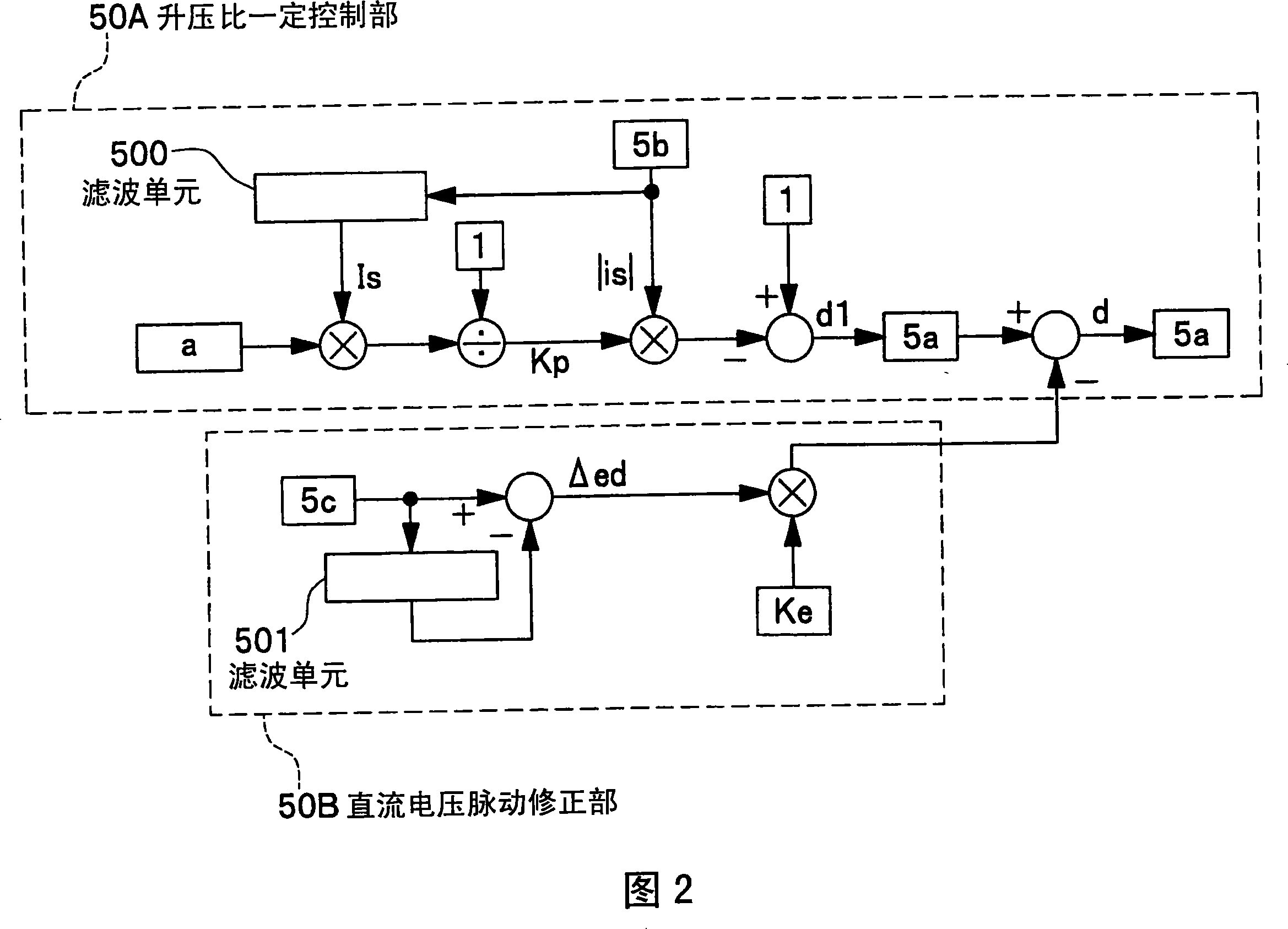
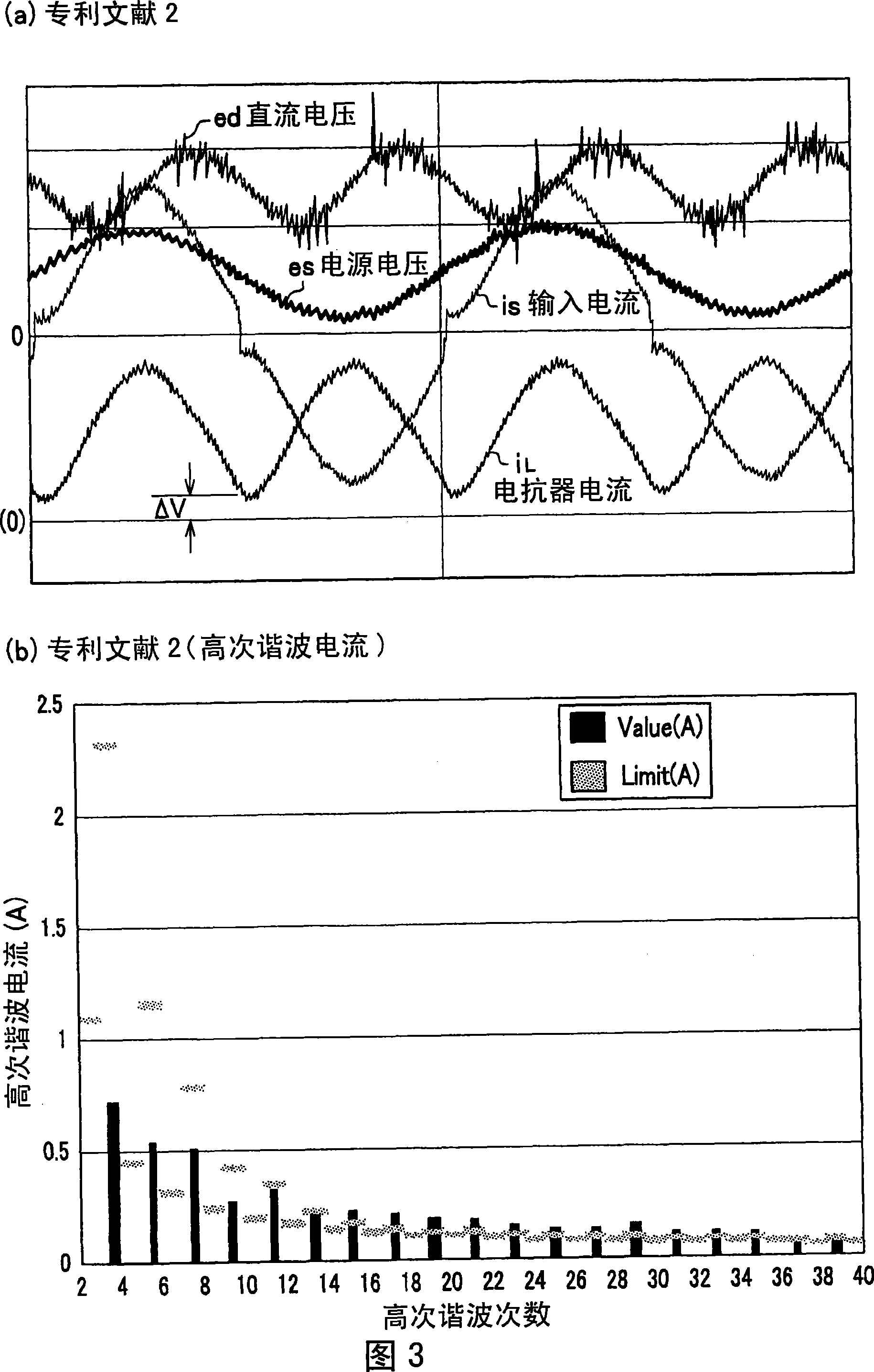
[0035] A first embodiment of the present invention will be described with reference to FIGS. 1 to 5 . FIG. 1 is a configuration diagram of a power supply circuit according to this embodiment, FIG. 2 is a configuration block diagram showing control contents, FIGS. 3 and 4 are operation waveforms, and FIG. 5 is an external view showing an example of a usage method of a control circuit used in a power supply circuit. .
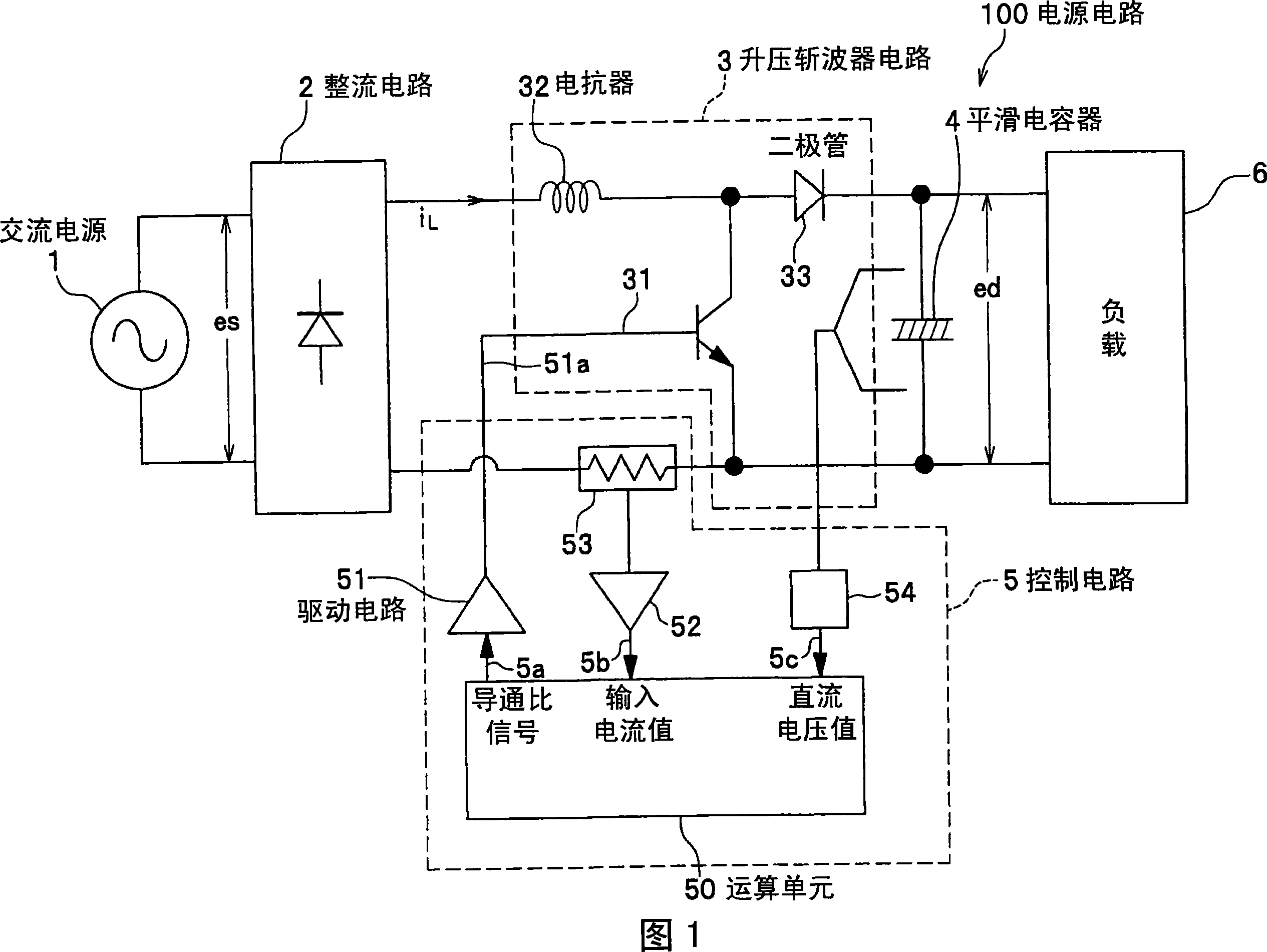
[0036] First, the configuration and operation of the power supply circuit will be described using FIG. 1 . The power supply circuit 100 is connected to an AC power supply 1, includes a rectification circuit 2 to which an AC voltage es is input, a step-up chopper circuit 3, a smoothing capacitor 4, and a control circuit 5, and supplies DC power to a load 6 connected to an output terminal of the smoothing capacitor 4. .
[0037] Here, the step-up chopper circuit 3 includes a reactor 32 connected to a rectifier circuit at one end, a diode 33 having an anode connec...
no. 2 approach
[0095] Next, the configuration of the second embodiment will be described with reference to FIGS. 6 to 8 .
[0096] FIG. 6 is a configuration diagram of the present embodiment, FIG. 7 is an explanatory diagram of the operation of changing the boosting ratio in a load state, and FIG. 8 is an external view showing an example of the utilization mode of the present embodiment. Hereinafter, the same symbols are assigned to the same components as those in the first embodiment, and description thereof will be omitted.
[0097] The structure of FIG. 6 is: a motor drive circuit including a motor 9 and an inverter circuit 8 is connected, and as a load of the power supply circuit of the present embodiment, the control circuit of the power supply circuit of the present embodiment and the control circuit of the inverter circuit are integrated. change. In other words, the control circuit 7 shown in FIG. 6 uses a microcomputer, and a single microcomputer controls the power supply circuit an...
no. 3 approach
[0113] A third embodiment of the present invention will be described using FIGS. 9 and 10 . The configuration of the power supply circuit of this embodiment is the same as that described with reference to FIG. 1 , and the only difference lies in the internal configuration of the arithmetic unit 50 .
[0114] FIG. 9 shows a configuration block diagram of this embodiment, and FIG. 10 shows an operation waveform when this embodiment is used. In this embodiment, when the step-up ratio constant control method shown in the first embodiment is used, the pulsating component of the DC voltage is used to stop the switching operation in the second half of each half cycle of the power supply cycle, so that in Patent Document 2 Based on the described technology and the configuration of the first embodiment, the efficiency of the power supply circuit can be improved. In addition, in the present embodiment, the above-described constant boost ratio control method has been described as a basi...
PUM
 Abstract
Description
Claims
Application Information
 - R&D
- Intellectual Property
- Life Sciences
- Materials
- Tech Scout
- Unparalleled Data Quality
- Higher Quality Content
- 60% Fewer Hallucinations
Browse by: Latest US Patents, China's latest patents, Technical Efficacy Thesaurus, Application Domain, Technology Topic, Popular Technical Reports.
© 2025 PatSnap. All rights reserved.Legal|Privacy policy|Modern Slavery Act Transparency Statement|Sitemap|About US| Contact US: help@patsnap.com