
Image display method

A screen display and display technology, applied in the field of screen display, can solve the problems of the direction deviation of the expansion of the color gamut range, etc.

Inactive Publication Date: 2008-05-07
WINTEK CORP
View PDF1 Cites 14 Cited by
  • Summary
  • Abstract
  • Description
  • Claims
  • Application Information

AI Technical Summary

Problems solved by technology

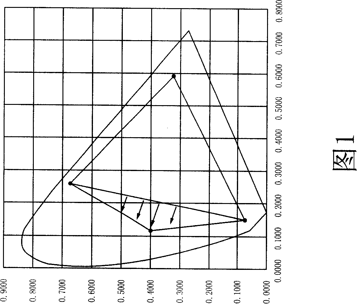
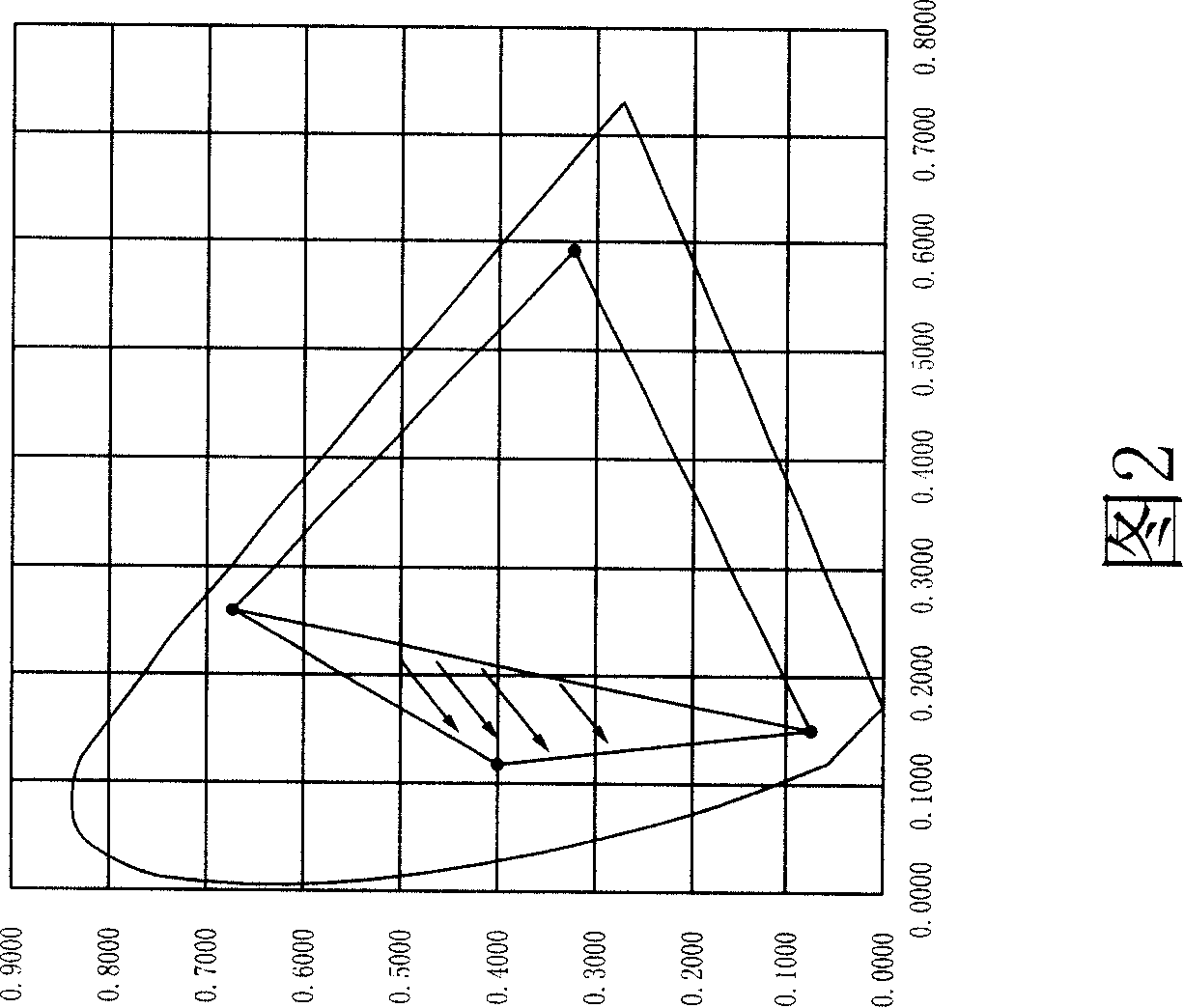
In addition, since the pixel penetration area is proportional to the brightness, when the area of ​​G is smaller than B, the direction of color gamut expansion will deviate from the blue area instead of linear expansion.

Method used


Image

  • Image display method
  • Image display method
  • Image display method

Examples


Embodiment Construction

[0033] In order to have a further cognition and understanding of the features, purposes and functions of the present invention, the detailed description is as follows in conjunction with the accompanying drawings:

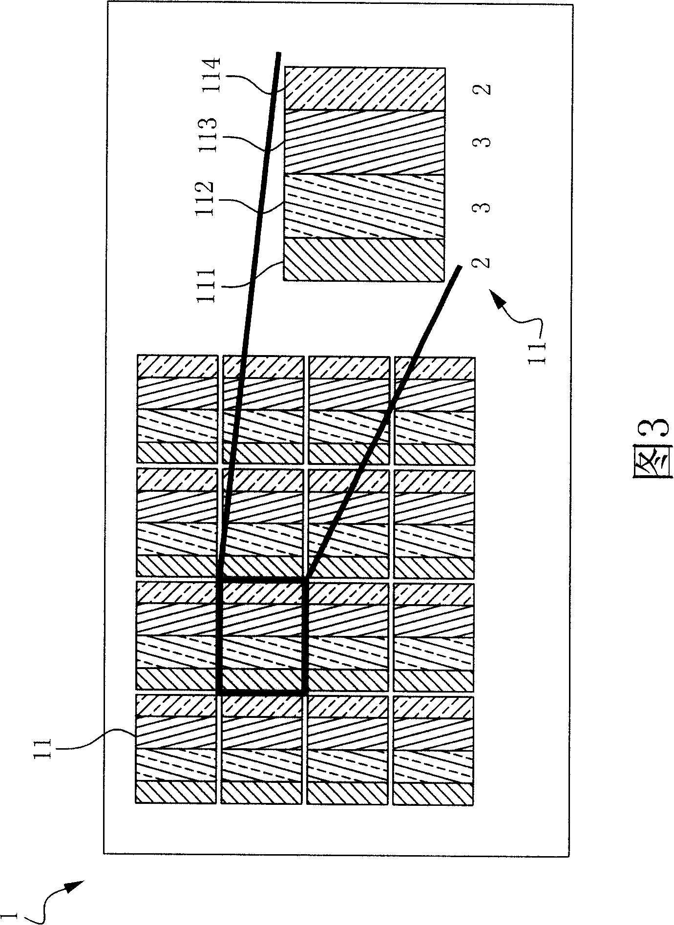
[0034] Please refer to FIG. 3 , which is a schematic diagram of a preferred embodiment of the color filter device of the present invention. In this figure, the left figure is a structural diagram of the color filter device, and the right figure is a partial enlarged view of the left figure. In this embodiment, in order to achieve the purpose of increasing the color gamut, each pixel 11 of the color filter device 1 is composed of a red sub-pixel 111, a green sub-pixel 112, a blue sub-pixel 113 and a color mixing sub-pixel The pixel 114 is formed, wherein the color-mixing sub-pixel 114 is formed by mixing any two of the red, green and blue sub-pixels. In this embodiment, in order to obtain a wider color gamut range, the green sub-pixel 112 adopts a green material wh...


PUM


Abstract

The invention relates to a screen display method. The invention is characterized in that each pixel comprises a red sub-pixel, a green sub-pixel, a blue sub-pixel and a mixed color sub-pixel that is mixed by any two sub-pixels from red, green and blue sub-pixels. The color filter device chooses the materials with excellent color saturation as the sub-pixels to upgrade color range and keeps white balance status by adjusting the area of the sub-pixels and matching a specific arithmetic simultaneously.

Description

technical field [0001] The invention relates to a picture display method, in particular to a picture display method for calculating sub-pixel output values ​​of a color filter device. Background technique [0002] With the advancement of science and technology, in recent years, most electronic devices are light, thin and small as the main appeal. Among them, liquid crystal display is not only mature in technology but also has many participating manufacturers, so its market share has an absolute advantage. However, since the liquid crystal molecules in the liquid crystal display do not have luminous properties, a backlight and a color filter must be used to enable the display to display color images. [0003] Each pixel of a conventional color filter is composed of three sub-pixels of R, G, and B. Therefore, when light sources of different intensities pass through these sub-pixels and mix colors, the pixels can display different colors and brightness. However, the color filt...

Claims


Application Information

Patent Timeline
IPC IPC(8): G09G3/34G09G3/36G09G5/02G02F1/13
Inventor 黄俊铭林林王伯贤林汉昌陈炫仰范倩彧黄俊纲
Owner WINTEK CORP
Learn More