A bridge soft shutdown circuit

A soft shutdown and circuit technology, applied to electrical components, electronic switches, conversion equipment with intermediate conversion to AC, etc., to achieve the effect of enhancing reliability and eliminating voltage spikes

Inactive Publication Date: 2008-04-30
ASTEC POWER SUPPLY (SHENZHEN) CO LTD
View PDF0 Cites 12 Cited by
  • Summary
  • Abstract
  • Description
  • Claims
  • Application Information

AI Technical Summary

Problems solved by technology

[0005] The technical problem to be solved by the present invention is to provide a bridge type soft shutdown circuit that can solve the shutdown stress in view of the defect that shutdown stress may occur in the prior art

Method used


Image

  • A bridge soft shutdown circuit
  • A bridge soft shutdown circuit
  • A bridge soft shutdown circuit

Examples


Embodiment Construction

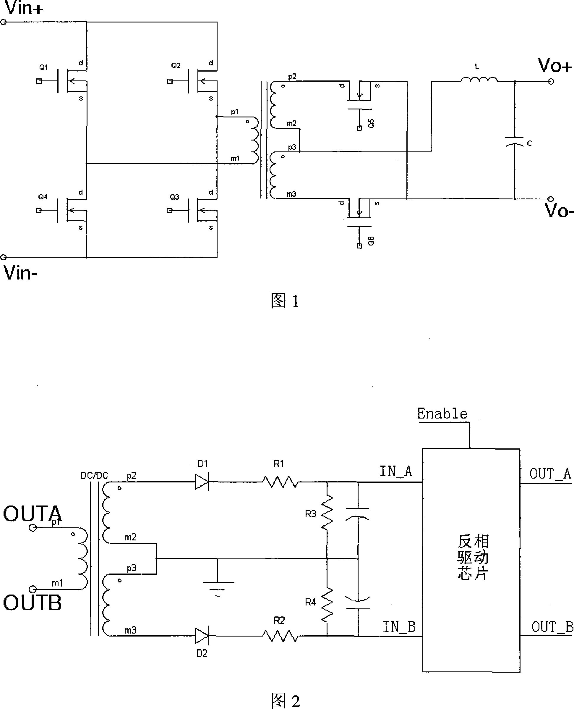
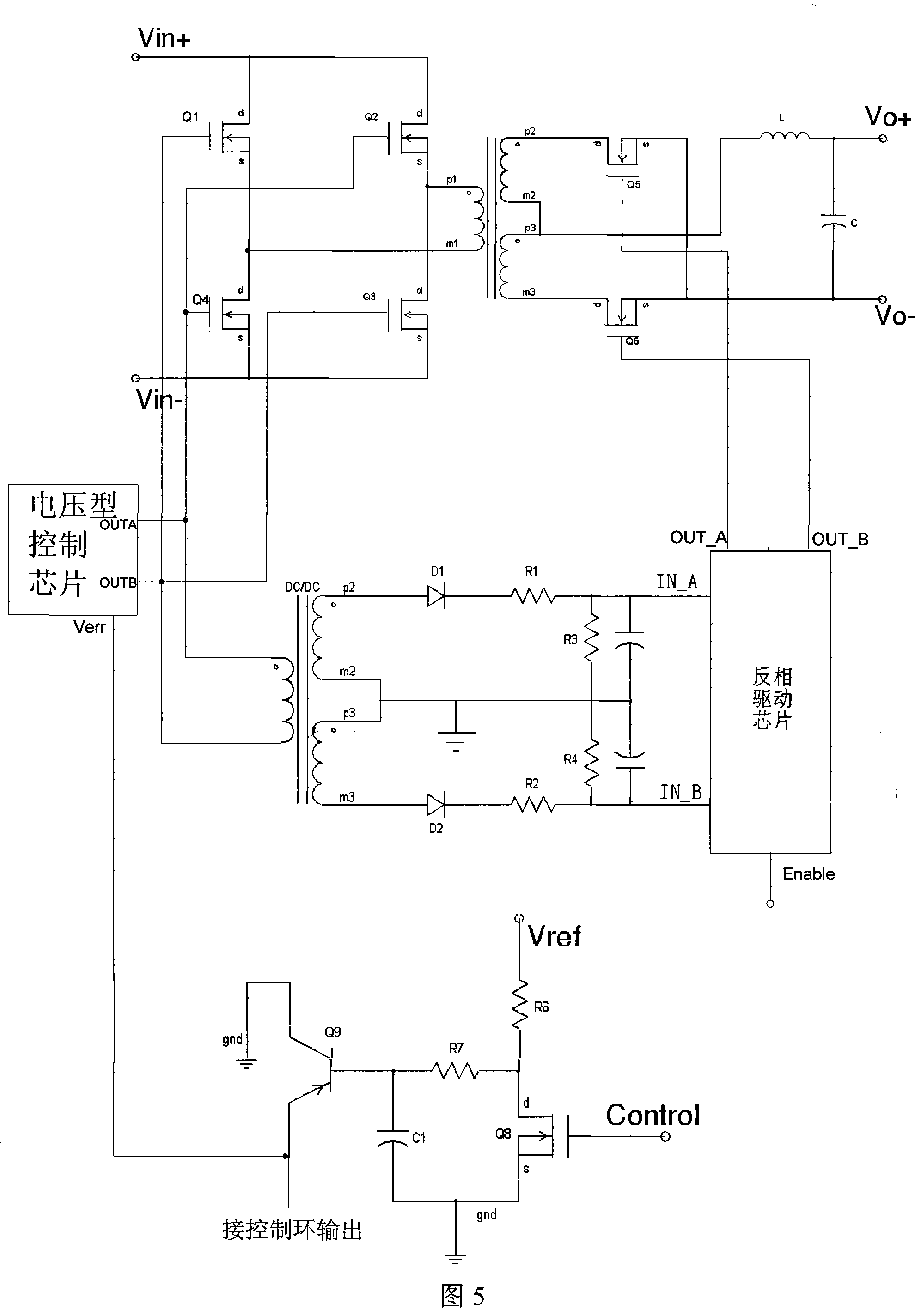
[0021] As shown in Fig. 4, in the schematic circuit diagram of the bridge type soft shutdown circuit of the present invention, it includes a PNP transistor Q9 and a charging and discharging circuit composed of a capacitor C1, resistors R6, R7 and an N-channel MOS transistor Q8. In this embodiment, the emitter of the transistor Q9 is connected to the error signal terminal Verr of the external control chip, and the collector is connected to the ground; in the charging and discharging circuit, one end of the resistor R7 is connected to the base of the transistor Q9, and the other end is connected to the MOS The drain of the transistor Q8; one end of the resistor R6 is connected to the auxiliary power supply Vref, and the other end is connected to the drain of the MOS transistor Q8; one end of the capacitor C1 is connected to the base of the transistor Q9, and the other end is connected to the ground; the source of the MOS transistor Q8 The pole is connected to the ground, and the ...


PUM


Abstract

The invention relates to a bridge-type soft shutdown circuit, the input terminal is connected to an external shutdown control signal, and the output terminal is connected to the error signal terminal of the external control chip, including: a triode, the emitter of which is electrically connected to the error signal of the control chip terminal, the collector is grounded; a charging and discharging circuit, which outputs a high voltage to the base of the transistor during normal operation and outputs a low voltage to the base of the transistor according to the external shutdown control signal. The circuit cooperates with the full-bridge synchronous rectification main circuit and the secondary side drive circuit, which eliminates the voltage spike on the synchronous rectifier tube on the secondary side of the full-bridge synchronous rectification main circuit during shutdown, and enhances the reliability of the system.

Description

technical field [0001] The invention relates to synchronous rectification technology, more specifically, to a bridge type soft shutdown circuit. Background technique [0002] As shown in FIG. 1 , it is an ordinary full-bridge circuit in which the secondary side adopts synchronous rectification technology. In order to improve the efficiency of the converter, when the four MOS transistors Q1, Q2, Q3, and Q4 on the primary side are all turned off, it is hoped that the synchronous rectifier transistors Q5 and Q6 on the secondary side will conduct freewheeling at the same time, so the generator shown in Figure 2 is adopted The circuit diagram of the driving signal of the secondary synchronous rectifier. The output PWM signals of the control chip are OUTA and OUTB, among which OUTA generates the driving signals of the primary side in charge of Q2 and Q4, OUTB generates the driving signals of the primary side of Q1 and Q3, and the secondary synchronous rectifier drive signals OUT_...

Claims


Application Information

Patent Timeline
Patent Type & Authority Applications(China)
IPC IPC(8): H02M3/22H03K17/687
Inventor 刘金云李静唐华张学
Owner ASTEC POWER SUPPLY (SHENZHEN) CO LTD
Why Eureka
Try Eureka