Valve moving device for internal combustion engine

A transmission device and internal combustion engine technology, applied in the direction of valve drive devices, internal combustion piston engines, valve devices, etc., can solve the problems of limited degrees of freedom, difficulty in stopping, etc., and achieve the effect of improving the degree of freedom

Inactive Publication Date: 2008-04-23
TOYOTA JIDOSHA KK
View PDF4 Cites 10 Cited by
  • Summary
  • Abstract
  • Description
  • Claims
  • Application Information

AI Technical Summary

Problems solved by technology

In the structure in which the valve body of multiple cylinders is driven by a motor, when the operation of all cylinders or part of the cylinders is controlled to stop, since the valve body for driving multiple cylinders is provided on the camshaft, it is difficult to adjust the valve body at any position. valve body to stop any cylinder
Therefore, there arises a problem that the degree of freedom of the operation of stopping all cylinders or reducing the number of cylinders, and even the degree of freedom of the valve closing control for suppressing catalyst deterioration during fuel cut is limited.

Method used


Image

  • Valve moving device for internal combustion engine
  • Valve moving device for internal combustion engine
  • Valve moving device for internal combustion engine

Examples


Embodiment approach 3

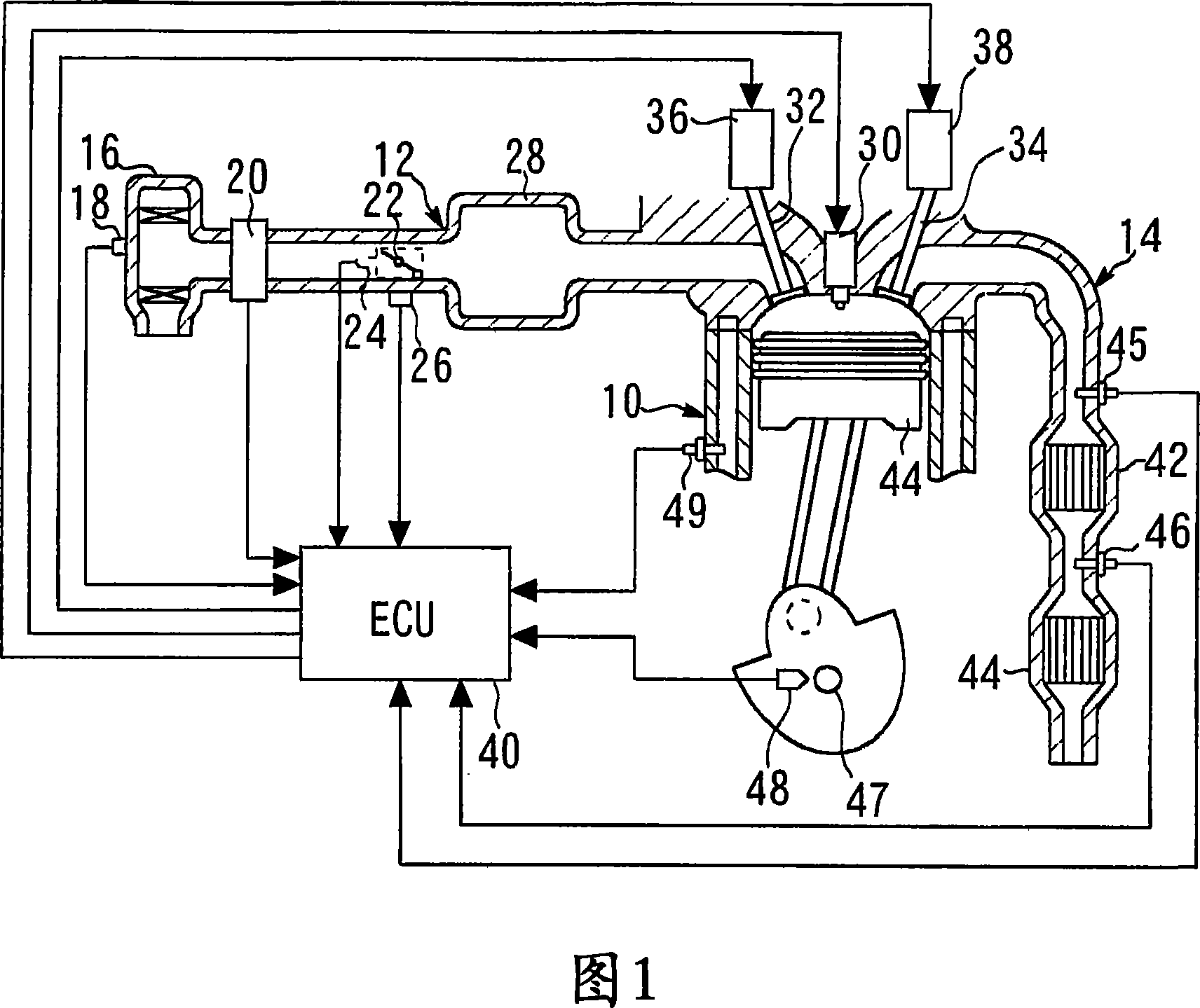
[0199] Next, Embodiment 3 of the present invention will be described. In Embodiment 3, the oxygen storage amounts of the catalysts 42 and 44 are reasonably controlled during the fuel-cut operation according to the driving of the intake valve 32 and the exhaust valve 34 .

[0200] In the system shown in FIG. 1 , the amount of oxygen stored in the catalysts 42 , 44 varies depending on the operating state of the internal combustion engine 10 . For example, when the air-fuel ratio is controlled to be lean, the oxygen storage amount of the catalysts 42 and 44 increases because the amount of oxygen in the exhaust gas increases. On the other hand, when the control to make the air-fuel ratio rich is performed, reducing components in the exhaust gas increase, and since oxygen is released from the downstream side catalysts 42 and 44, the oxygen storage amount decreases.

[0201] In particular, when the fuel increase control such as power increase is performed, the exhaust air-fuel rati...


PUM


Abstract

A valve moving device (36) for an internal combustion engine, where a valve body (32) of each cylinder is opened and closed by a motor. The valve moving device (36) has a cam shaft (60) rotated by a motor (50D) and having cams (64) for driving the valve bodies (32) of the cylinders, a control means for driving the motor (50D) while switching a drive mode between a normal rotation drive mode where the cam shaft (60) is continuously rotated in one direction to drive the valve bodies (32) and a rocking drive mode where the cam shaft (60) is rocked to drive the valve bodies (32), and a variable means for varying, when the mode is switched, a relative angular position of the cam (64), provided on the cam shaft (60), corresponding to each cylinder.

Description

technical field [0001] The invention relates to a valve train for an internal combustion engine. Background technique [0002] Conventionally, there is known a technique described in, for example, Japanese Patent Laid-Open No. 2004-183610 , in which an intake valve and an exhaust valve provided in each cylinder are driven by an electric motor. [0003] Also, Japanese Patent Application Laid-Open No. 2005-171937 describes a method of operating a motor in a swing drive mode in which the rotation direction of the camshaft is switched in the lift of the valve body. [0004] As documents related to the present invention, the applicant read the following documents. [0005] Patent Document 1: Japanese Patent Laid-Open No. 2004-183610 [0006] Patent Document 2: Japanese Patent Laid-Open No. 2005-171937 [0007] Patent Document 3: Japanese Patent Laid-Open No. 2004-165704 [0008] Patent Document 4: Japanese Patent Laid-Open No. 2004-143990 [0009] However, in the conventiona...

Claims


Application Information

Patent Timeline
IPC IPC(8): F01L9/04F01L1/04F01L1/02F01L9/20
CPCY02T10/18
Inventor 江崎修一
Owner TOYOTA JIDOSHA KK
Why Eureka
Try Eureka