Eureka AIR delivers breakthrough ideas for toughest innovation challenges, trusted by R&D personnel around the world.

Light source lamp cooling mechanism and projection type image displaying device employing the same

A technology of cooling mechanism and light source lamp, which is applied in projection device, cooling/ventilation/heating transformation, optics, etc., can solve the problem that it is difficult to realize high output power of light source at the same time, small and lightweight devices, and achieve high output power and high efficiency Effect of cooling, small ventilation resistance

Active Publication Date: 2008-04-23
SANYO ELECTRIC CO LTD
View PDF1 Cites 15 Cited by
  • Summary
  • Abstract
  • Description
  • Claims
  • Application Information

AI Technical Summary

Problems solved by technology

Projection-type image display devices such as liquid crystal projectors have been required to achieve both high output power of the light source and light weight of the device. In the above-mentioned conventional technologies, a high-power fan is required to cool the high-power light source lamp, and the size of the fan is increased. , it is difficult to achieve high output power of the light source and light weight of the device at the same time

Method used


Image

  • Light source lamp cooling mechanism and projection type image displaying device employing the same
  • Light source lamp cooling mechanism and projection type image displaying device employing the same
  • Light source lamp cooling mechanism and projection type image displaying device employing the same

Examples


Embodiment Construction

[0015]

Hereinafter, embodiments of the invention of the present application will be described in detail with reference to the drawings.

[0016]

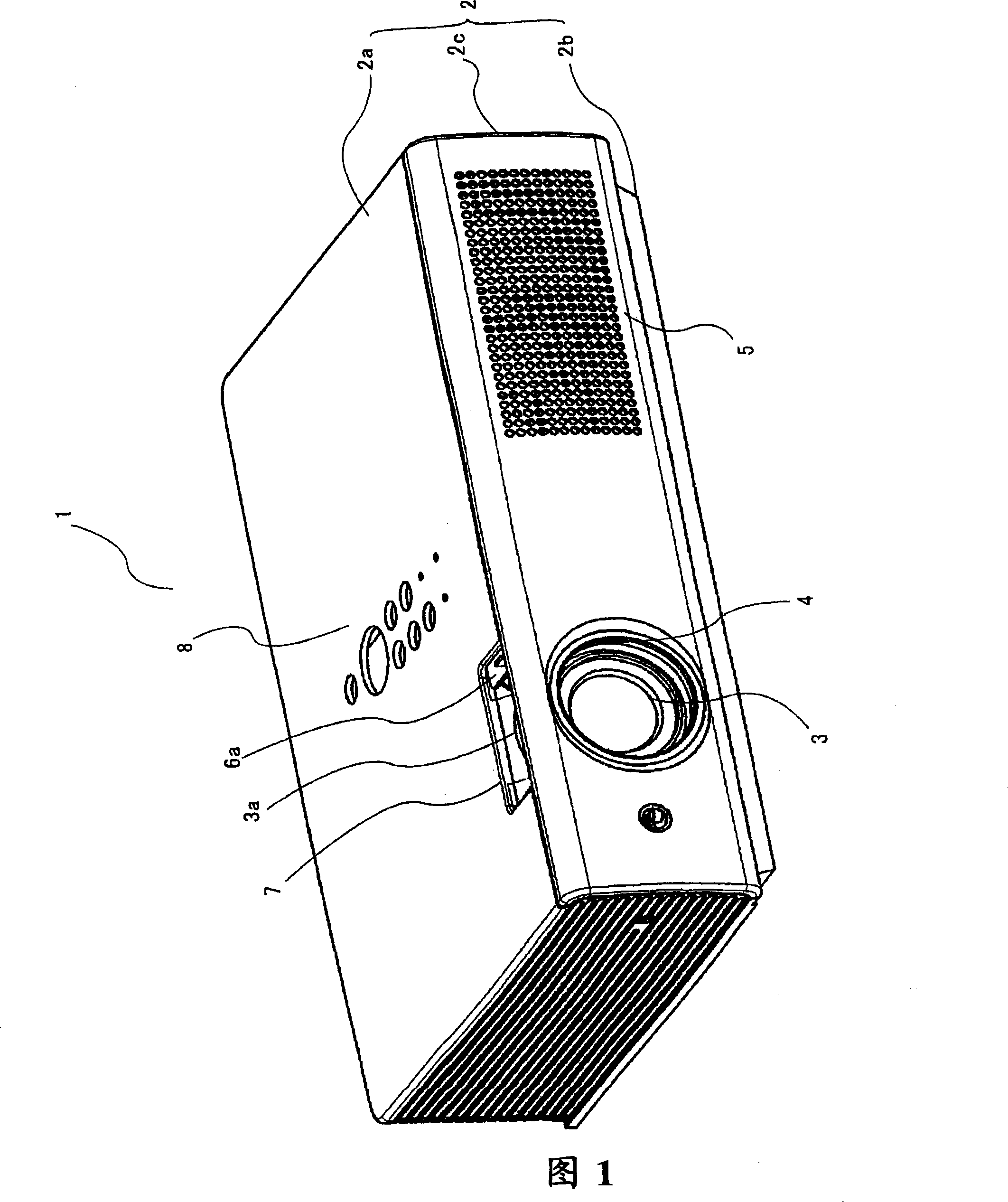
Fig. 1 is a perspective view of a liquid crystal projector as one embodiment of the projection type image display device of the invention of the present application as viewed obliquely from above, and Fig. 2 is a perspective view of the upper case, front case, main control board, etc. removed from it. Perspective view from the back side obliquely from above.

[0017]

As shown in Figure 1, the external cabinet 2 that constitutes the outer profile of the liquid crystal projector 1 is composed of an upper cabinet 2a, a lower cabinet 2b, and a front cabinet 2c. The upper cabinet 2a and the front cabinet 2c are removed, and the main cabinet 2a and front cabinet 2c are removed. The control board (not shown), etc., appears inside as shown in Figure 2.

[0018]

Viewed from the front side of the front cabinet 2c, a projection window 4 through ...


PUM


Abstract

A projection type image display apparatus of the invention is equipped with a lamp cooling mechanism, which has a duct ( 121 ) for guiding the air sent from an air intake fan ( 12 ) in the forward direction from a position lateral to a lamp ( 16 ). The duct ( 121 ) has a curved wall ( 122 ) for directing the air in the duct ( 121 ) to the air intake port ( 164 ) formed near the open end of the lamp ( 16 ). The lamp cooling mechanism has a further guide plate ( 123 ) for spreading the air stream directed by the curved section ( 122 ) over the region from the tip ( 161 b) to the luminous section ( 161 a) of the lamp ( 16 ). As a consequence, relevant sections of the lamp can be efficiently cooled, thereby simultaneously enabling uprating of power of the light source unit and downsizing and lightening of the image display apparatus without supplying the fan with a large amount of power.

Description

Technical field [0001] The invention relates to a light source lamp cooling mechanism and a projection type display device using the mechanism. Background technique [0002] In projection image display devices such as liquid crystal projectors, high-temperature, high-luminance high-pressure mercury lamps or metal halide lamps are used as the light source. Since the highest temperature reaches around 1000°C, the light source is cooled by air from a fan. . [0003] Patent Document 1 discloses a structure in which air from a fan is blown laterally from the front of the light source lamp toward an intake port formed at the edge of the opening of the reflector to cool the light source lamp. [Patent Document 1] JP 5-135745 A [0004] However, in the technique of Patent Document 1 described above, since only the air intake port formed at the edge of the opening of the reflector is blown laterally, the air blown from the intake port is blown to the lateral direction without being di...

Claims


Application Information

Patent Timeline
Patent Type & Authority Applications(China)
IPC IPC(8): G03B21/16H05K7/20G03B21/00
CPCG03B21/16
Inventor 中川则夫久保敦志
Owner SANYO ELECTRIC CO LTD
Why Eureka
Eureka Blog
Learn More