
Patsnap Eureka
For R&D, Patsnap Eureka makes reading and utilizing patents & technical documents easy.
Patsnap Eureka AIR
Designed for self-driven R&D workflows. Generate viable solutions, solve complex R&D challenges, empower your innovation with AI.

Patsnap Eureka Materials
Designed for material experts only. Revolutionize your material R&D, from search, analyze, to developing new materials.

TechResearch
Generate reliable direction feasibility study reports for your R&D in just a few steps.

TechSeek
Discover and master advanced knowledge NOW. Basics, ideas, possibilities, all at once.

TechMind
As an expert in R&D Theories, TechMind can generates customized viable solutions instantly.

TechRisk
Analyze your overall solution with one click, know your potential R&D risks in advance.

TechMonitor
Get weekly tech updates, stay abreast of the latest tech innovations and key insights.
Linear motor and machine tool having the same mounted thereon
一种线性电动机、动作的技术,应用在机床领域,能够解决结构变复杂、零部件数量增加等问题,达到简单结构、防止落下、结构紧凑的效果
- Summary
- Abstract
- Description
- Claims
- Application Information
AI Technical Summary
Problems solved by technology
Method used
Image


Examples
Embodiment Construction
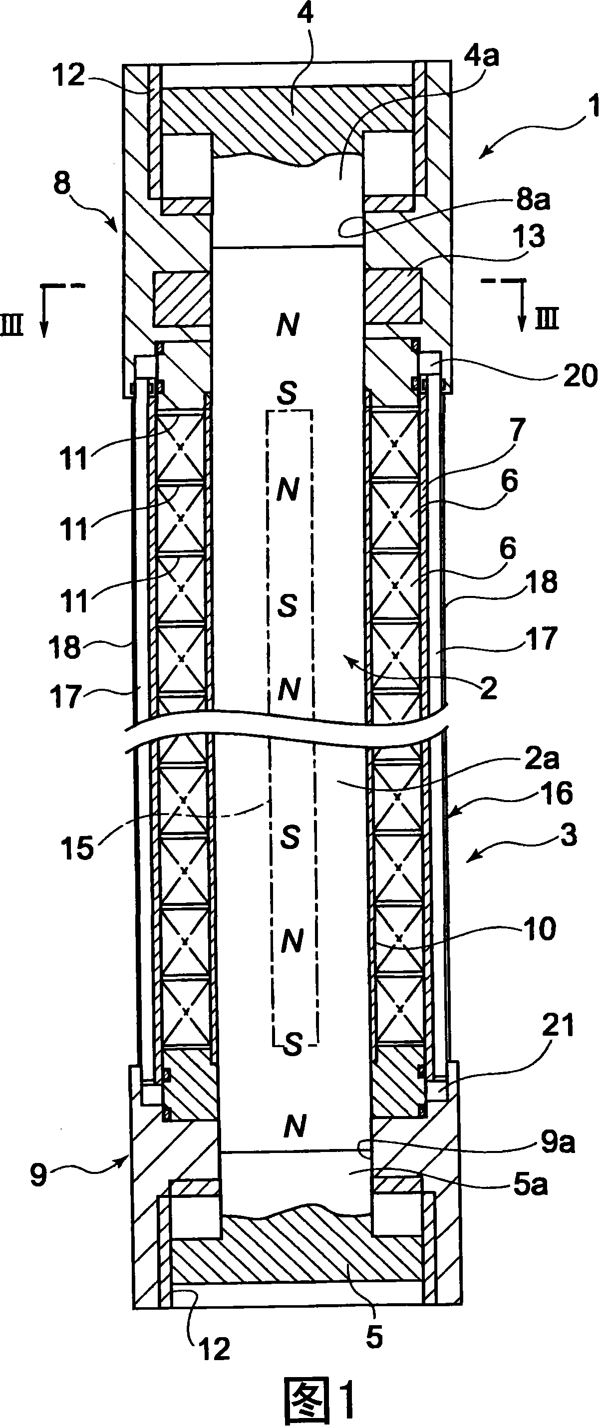
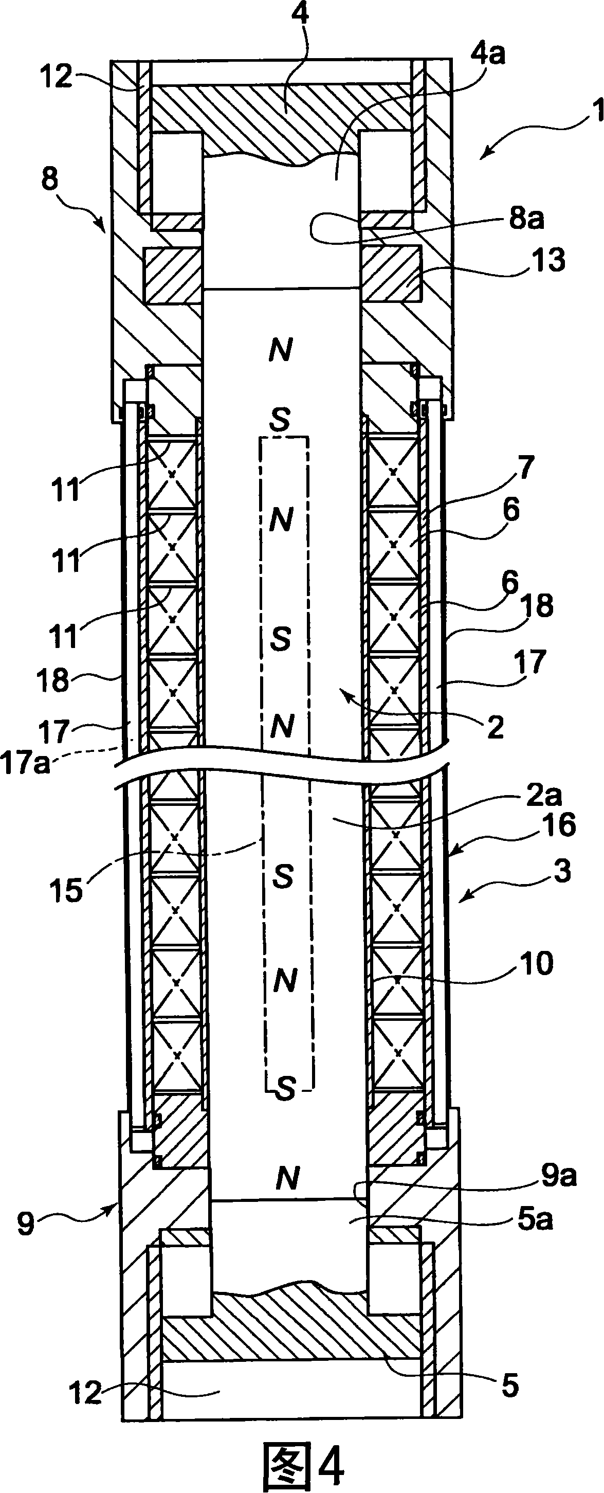
[0024] Next, a first embodiment of the present invention will be described with reference to FIGS. 1 to 3 . This linear motor 1 includes a magnet member 2 and a coil member 3. The magnet member 2 is composed of permanent magnets whose N poles and S poles are alternately arranged in a predetermined axial direction. The coil member 3 surrounds the magnet member 2. The magnet member 2 is allowed to move relatively freely in the axial direction inside. The coil member 3 is a stator, and the magnet member 2 is a moving body.
[0025] The magnet member 2 is a member in which sliders 4, 5 are attached to both ends of a magnet member main body 2a made of a round bar-shaped permanent magnet.
[0026] The coil member 3 has a structure in which a plurality of cylindrical coils 6 surrounding the magnet member 2 are arranged in an axial direction. The plurality of coils 6 described above are housed in a common cylindrical coil case 7 , and caps 8 and 9 are attached to both ends of the co...
PUM
 Abstract
Description
Claims
Application Information
 - R&D Engineer
- R&D Manager
- IP Professional
- Industry Leading Data Capabilities
- Powerful AI technology
- Patent DNA Extraction
Browse by: Latest US Patents, China's latest patents, Technical Efficacy Thesaurus, Application Domain, Technology Topic, Popular Technical Reports.
© 2024 PatSnap. All rights reserved.Legal|Privacy policy|Modern Slavery Act Transparency Statement|Sitemap|About US| Contact US: help@patsnap.com