Light source used for laser display
A technology of light source device and laser display, which is applied in the direction of lighting device, coupling of optical waveguide, components of lighting device, etc., to achieve the effect of reducing cost, improving output power, improving reliability and maintainability
- Summary
- Abstract
- Description
- Claims
- Application Information
AI Technical Summary
Problems solved by technology
Method used
Image

Examples
Embodiment 1
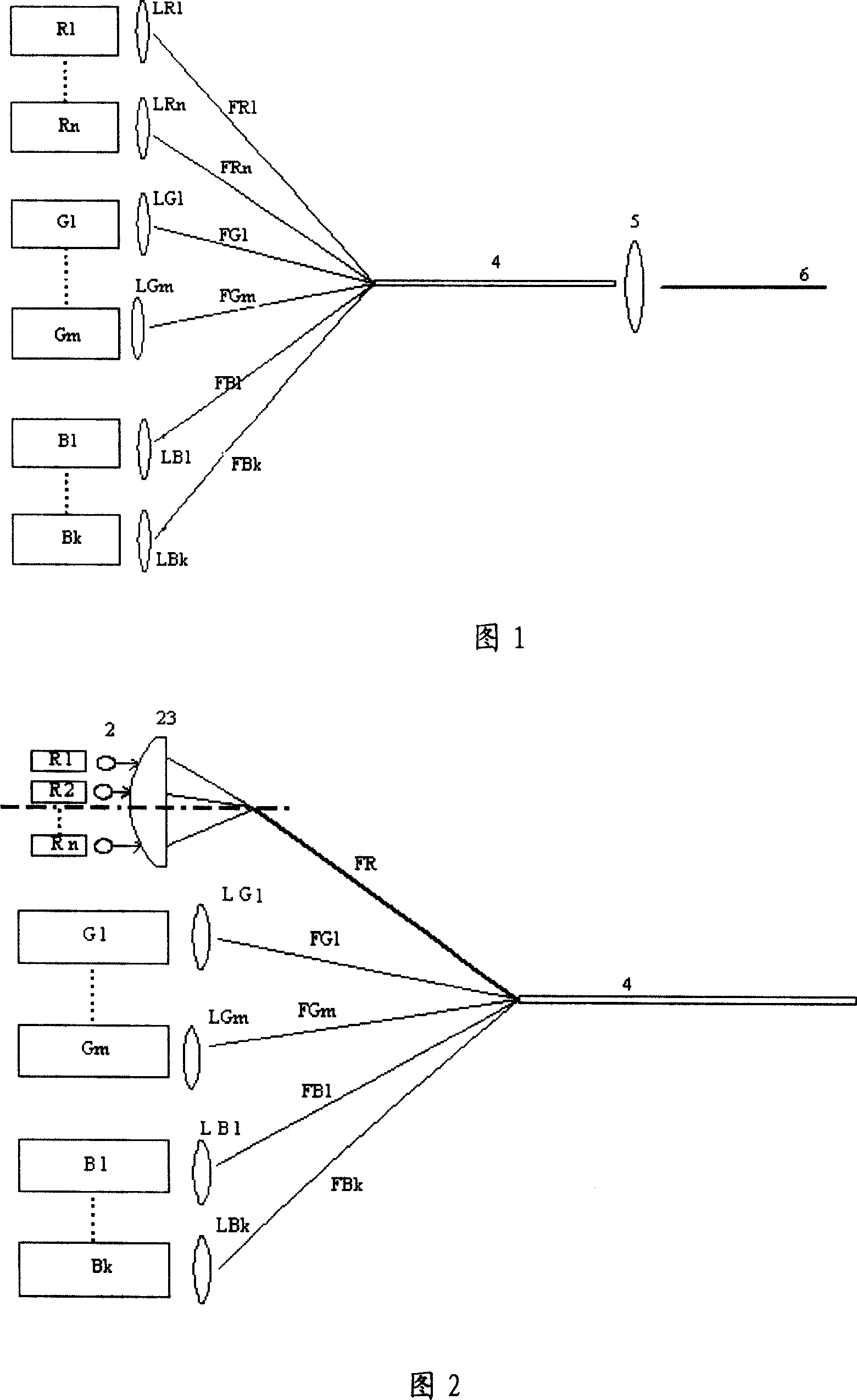
[0025] As shown in Figure 1, the light source device used for laser display, the light source includes a red laser light source composed of n red solid-state lasers, represented by Rl-Rn in Figure 1, and a green light composed of m green solid-state lasers The laser light source, represented by G1-Gn in Figure 1, and the blue-ray laser light source composed of k blue solid-state lasers, represented by Bl-Bn in Figure 1, wherein the ratio between n, m, and k should be in accordance with the output power of each laser and display color ratio requirements to set, this is competent for those skilled in the art, such as the present embodiment selects n=6 red light solid-state lasers R1-R6 with a wavelength of 671nm and an output power of 5W; m =3 sets of green solid-state lasers G1-G3 with a wavelength of 532nm and an output power of 1W; and k=4 sets of blue solid-state lasers B1-B4 with a wavelength of 473nm and an output power of 1W.
[0026] The converging device of the present ...
Embodiment 2
[0029] As shown in Figure 2, the light source device for laser display, the light source includes a red laser light source composed of n red semiconductor lasers, represented by Rl-Rn in Figure 2, a green light composed of m green solid-state lasers Laser light source, represented by G1-Gn in Figure 2, and a blue laser light source composed of k blue solid-state lasers, represented by Bl-Bn in Figure 2, wherein the ratio between n, m, and k should be in accordance with the output of each laser Power and display color matching requirements are set, which is competent for those skilled in the art. For example, in this embodiment, n=112 red light semiconductor lasers R1- R112; m=12 green solid-state lasers G1-G12 with a wavelength of 532nm and an output power of 1W and k=3 blue solid-state lasers B1-B3 with a wavelength of 457nm and an output power of 3W. All lasers are placed in parallel.
[0030] The converging device of this embodiment includes a plurality of converging lenses...
Embodiment 3
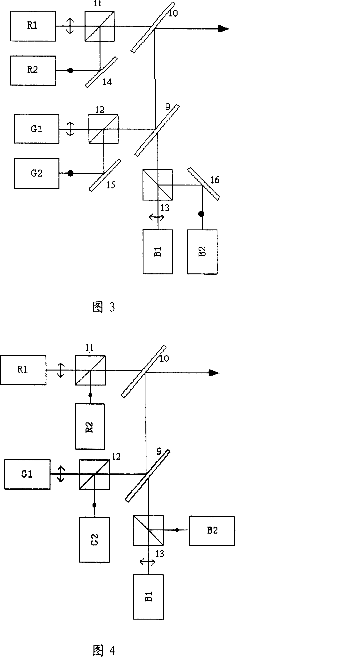
[0035] In the high-power laser display light source provided in this embodiment, the RGB three-color light sources are composed of two lasers placed in parallel, and the outgoing lights are p-polarized light and s-polarized light, respectively, as shown in Figure 3, R1 and R2 are wavelengths 660nm red semiconductor laser with an output power of 12W; G1 and G2 are green solid-state lasers with a wavelength of 532nm and an output power of 3W; B1 and B2 are blue solid-state lasers with a wavelength of 457nm and an output power of 2W; among them, R1 and G1 The lasers emitted by R1 and B1 are P-polarized light, and the lasers emitted by R2, G2 and B2 are S-polarized light.
[0036]In FIG. 3 , the beam combining system mainly includes a first polarizing beam splitter 11 , a second polarizing beam splitter 12 , a third polarizing beam splitter 13 , a first color combining mirror 9 , and a second color combining mirror 10 .
[0037] Polarizing Beam Splitter (PBS for short) is combined...
PUM
 Abstract
Description
Claims
Application Information
 - R&D
- Intellectual Property
- Life Sciences
- Materials
- Tech Scout
- Unparalleled Data Quality
- Higher Quality Content
- 60% Fewer Hallucinations
Browse by: Latest US Patents, China's latest patents, Technical Efficacy Thesaurus, Application Domain, Technology Topic, Popular Technical Reports.
© 2025 PatSnap. All rights reserved.Legal|Privacy policy|Modern Slavery Act Transparency Statement|Sitemap|About US| Contact US: help@patsnap.com