Power transmission device

A kind of transmission device and power technology, applied in the direction of transmission device, chain/belt transmission device, control device, etc., can solve the problems such as difficult position adjustment, achieve the effect of narrowing width and improving motion performance

Inactive Publication Date: 2008-04-02
HONDA MOTOR CO LTD
View PDF1 Cites 1 Cited by
  • Summary
  • Abstract
  • Description
  • Claims
  • Application Information

AI Technical Summary

Problems solved by technology

In addition, when the balancer shaft is installed, it is difficult to adjust the position with the continuously variable transmission. When viewed from the side, the continuously variable transmission overlaps with the balancer shaft, and the lateral width of the power unit is wide.

Method used


Image

  • Power transmission device
  • Power transmission device
  • Power transmission device

Examples


Embodiment Construction

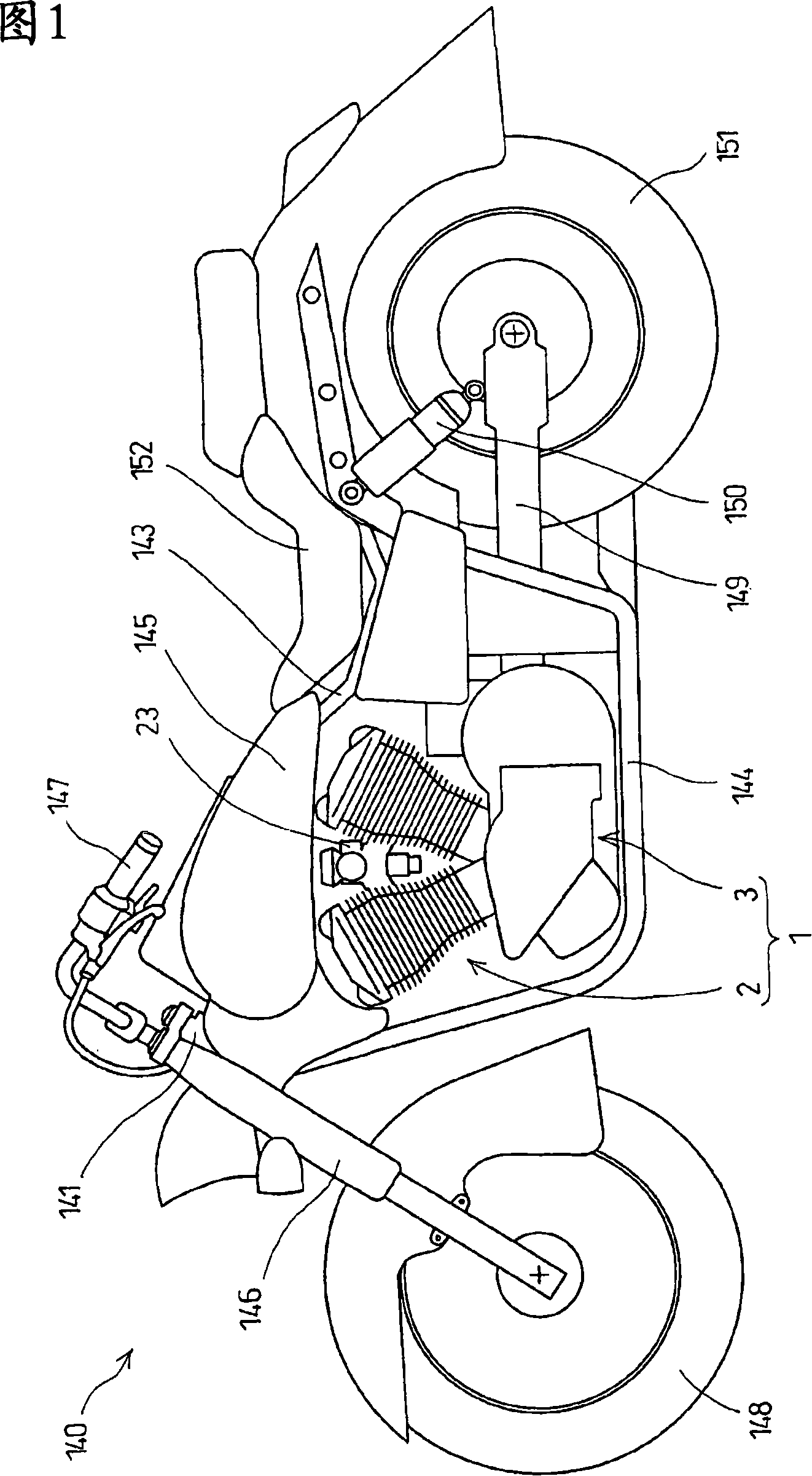
[0058] FIG. 1 is a side view of a motorcycle 140 equipped with a power unit 1 according to the present invention. The vehicle structure of the two-wheeled motorcycle 140 has a main frame (not shown) extending rearward from a front pipe 141 at the front end, and a rear frame 143 extending obliquely downward from the rear of the main frame. , The lower frame 144 protrudes downward from the front pipe 141 and extends rearward. The rear end portion of the lower frame 144 is bent upward and connected to the rear frame 143 . The fuel tank 145 is provided across the main frame (not shown). Between the main frame, the rear frame 143 and the lower frame 144, the power unit 1 integrating the internal combustion engine 2 and the transmission 3 is mounted. The front fork 146 is rotatably supported by the front pipe 141, a manipulation handle 147 is attached to the upper end thereof, and a front wheel 148 is supported via a shaft at the lower end thereof. A pair of rear fork 149, its fr...


PUM


Abstract

A power transmission device for transmitting power of an internal combustion engine of a motorcycle. By improving the arrangement of a continuously variable transmission, a balancer shaft and a drive pulley and a driven pulley of the continuously variable transmission, a lateral width and longitudinal length of a power unit are decreased thus making the power unit more compact. A continuously variable transmission is arranged behind a crankshaft, and a balancer is arranged between the continuously variable transmission and the crankshaft in a state wherein the balancer does not overlap the continuously variable transmission. A drive force of the crankshaft is transmitted to a drive pulley shaft of the continuously variable transmission by way of a gear of a balancer shaft. The approximate center of the crankshaft, the balancer and the respective pulleys of the continuously variable transmission are arranged on a vertical plane of a vehicle body center line.

Description

technical field [0001] The invention relates to a transmission device for transmitting the power of an internal combustion engine of a two-wheeled motorcycle to the rear wheel, in particular to a transmission device with a hydraulically controlled continuously variable transmission (Continuously Variable Transmission, referred to as CVT). Background technique [0002] In the past, since the driving pulley of the continuously variable transmission was provided at the shaft end portion on the extension line of the crankshaft, the lateral width of the power unit tended to be relatively wide. Also, when the balancer shaft is provided, positional adjustment with the continuously variable transmission is difficult, and the continuously variable transmission overlaps with the balancer shaft when viewed from the side, and the lateral width of the power unit is wide. In addition, the driving pulley and the driven pulley of the continuously variable transmission are generally configur...

Claims


Application Information

Patent Timeline
Patent Type & Authority Applications(China)
IPC IPC(8): B60K17/04B60K17/06B62M7/02B62M9/08F16H37/02
CPCF16H9/18B60K17/04
Inventor 小笠原敦三堀敏正
Owner HONDA MOTOR CO LTD
Why Eureka
Try Eureka