
Intelligent spiral bevel gear assembled milling cutter disc measuring and regulating instrument

A spiral bevel gear assembly technology, which is applied in the field of intelligent spiral bevel gear assembly milling cutter disc measurement and adjustment instrument, can solve the problems of long distance adjustment position, complicated adjustment process, and low measurement accuracy, so as to improve the accuracy and efficiency, the overall structure is simple, and the effect of broad market space

Inactive Publication Date: 2008-03-26
TIANJIN UNIVERSITY OF SCIENCE AND TECHNOLOGY +1
View PDF0 Cites 25 Cited by
  • Summary
  • Abstract
  • Description
  • Claims
  • Application Information

AI Technical Summary

Problems solved by technology

Its shortcomings are: 1. The measurement accuracy is low, it is difficult to achieve high-precision measurement, and it is difficult to achieve high-precision adjustment of the "assembled milling cutter head"; 2. The adjustment process is complicated, and the tool measurement position of the dual-probe tool adjustment instrument The distance from the tool adjustment position is far away, it is difficult to ensure the synchronization of measurement and adjustment, and the operation is more complicated; 3. The measurement data can only be read and recorded manually, and it is difficult to ensure the reliability and integrity of the data, and manual recording Measurement and adjustment data are difficult to meet the needs of digital manufacturing and digital management
[0006] Whether it is grinding, hard tooth surface scraping (fine milling), or grinding, there is a high precision requirement for the tooth surface finish of the spiral bevel gear formed during milling. In order to meet this requirement, on the one hand It is required to use high-precision gear milling machine tools; on the other hand, higher requirements are put forward for the precision of the gear milling cutters used in gear milling machine tools. The design, structure and function of the "knife adjustment instrument" are unsatisfactory
[0007] Through various literature searches at home and abroad, no instrument device and related research reports with the characteristics of the present invention are found

Method used


Image

  • Intelligent spiral bevel gear assembled milling cutter disc measuring and regulating instrument
  • Intelligent spiral bevel gear assembled milling cutter disc measuring and regulating instrument

Examples


Embodiment Construction

[0024] The composition of the present invention will be described in detail through specific embodiments below in conjunction with the accompanying drawings; however, the description of the embodiments of the present invention is illustrative rather than restrictive, and the scope of protection is subject to the content of the claims.

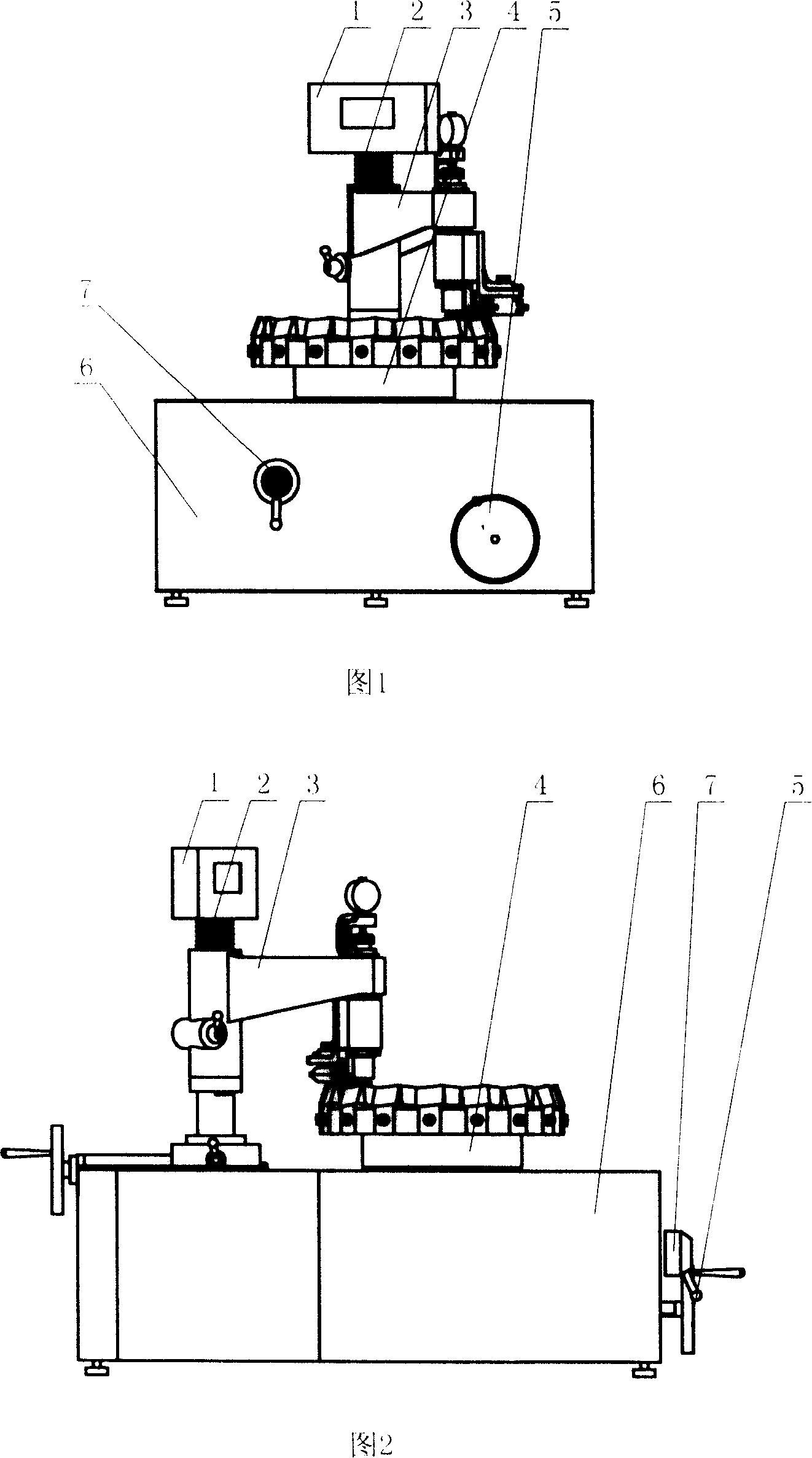
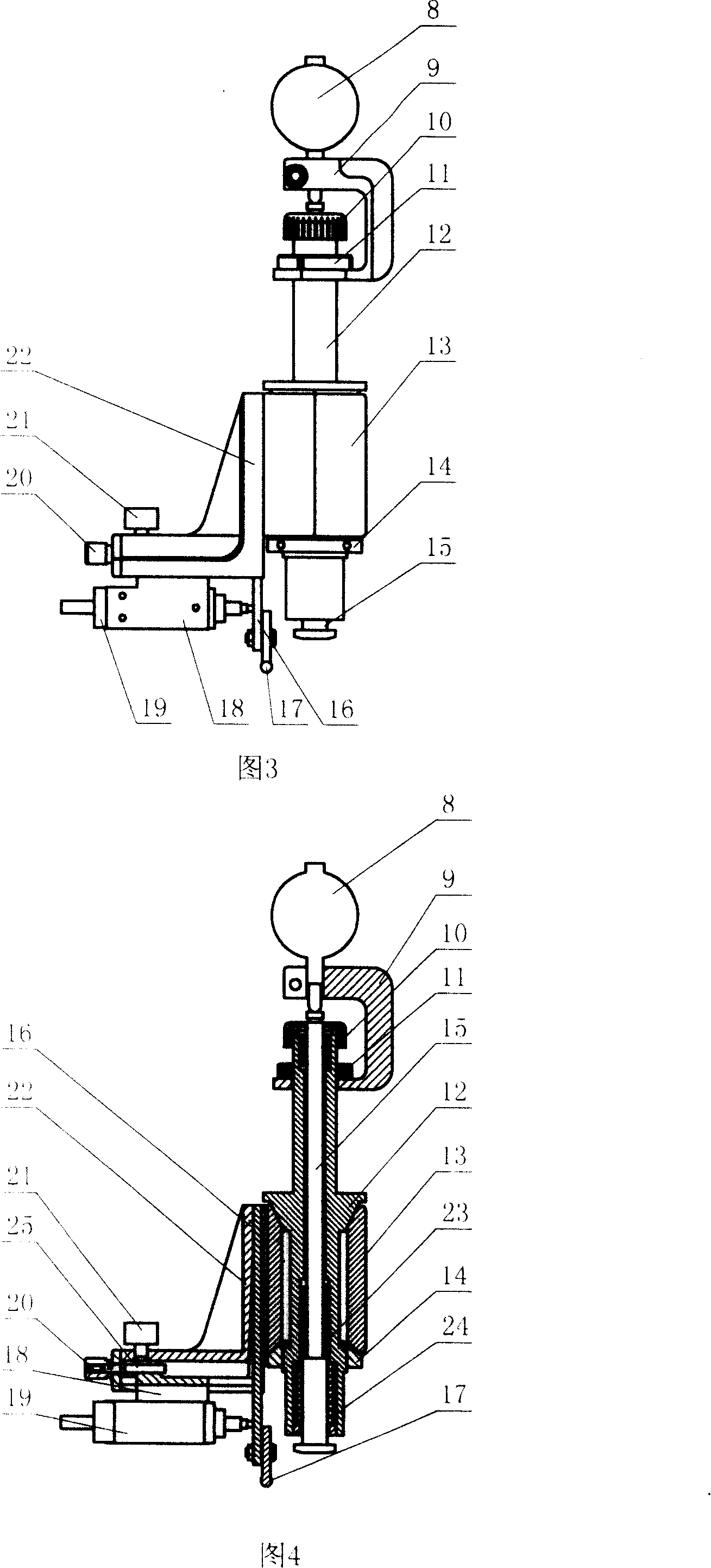
[0025] This intelligent spiral bevel gear assembled milling cutter head measuring and adjusting instrument has its main body (see Figure 1 and Figure 2) consisting of a machine base 6, a cutter head spindle 4, a column 2, a horizontal swing arm 3, a multimeter display box 1 and It consists of an integrated measuring head, in which the spindle of the cutter head and the column are respectively installed on the workbench of the machine base, and the clutch operating handle 7 and the hand wheel 5 are also installed on the machine base. The indicator box is installed on the top of the column, and the horizontal swing arm The front end of the integra...


PUM


Abstract

The present invention relates to one kind of intelligent measuring and regulating instrument for assembled milling cutter machining spiral bevel gear. Technologically, the intelligent measuring and regulating instrument includes one height measuring head with one digital dial gauge mounted in the end of the horizontal oscillation arm, and one radial measuring head with one digital dial gauge coaxially with the height measuring head. The measured data is stored, analyzed and processed in a computer and the processed result is shown in a display screen. The present invention can raise the milling cutter measuring and regulating precision and efficiency, and has simple structure and low manufacture cost.

Description

technical field [0001] The invention belongs to the field of detection instruments in the machinery industry, in particular to an intelligent spiral bevel gear assembly type milling cutter disc measuring and adjusting instrument used in the milling process of spiral bevel gears. Background technique [0002] Spiral bevel gears, also known as spiral bevel gears, occupy a considerable position in the machinery industry because of their good dynamic performance. Spiral bevel gears are widely used in industries such as automobiles, petrochemicals, metallurgy, and military machinery. The assembled milling cutter measuring and adjusting instrument used in the milling process of spiral bevel gears is the supporting testing equipment for spiral bevel gear milling machines. At present, the "tool adjustment instrument" used by domestic enterprises to measure and adjust assembled milling cutters adopts a discrete double-probe structure, that is: one set of probes is used for measuring ...

Claims


Application Information

Patent Timeline
Patent Type & Authority Applications(China)
IPC IPC(8): B23F23/12B23Q17/12B23Q17/22B23Q15/22
Inventor 于德敏王永强许增朴王在江
Owner TIANJIN UNIVERSITY OF SCIENCE AND TECHNOLOGY
Learn More