Strabism tester

A tester and eyeball technology, applied in the field of medical instruments, can solve the problems of systematic errors, inability to objectively record and analyze movement patterns, inability to observe both eyes at the same time, etc., and achieve the effect of accurate and objective results, improved efficiency and accuracy

Inactive Publication Date: 2008-03-26
THE FIRST AFFILIATED HOSPITAL OF THIRD MILITARY MEDICAL UNIVERSITY OF PLA
View PDF0 Cites 24 Cited by
  • Summary
  • Abstract
  • Description
  • Claims
  • Application Information

AI Technical Summary

Problems solved by technology

Most of these inspection methods are subjective psychophysical inspection methods. The examiner can only observe directly with the naked eye, and can only observe the movement of one eye at a time. They cannot observe both eyes at the same time...

Method used


Image

  • Strabism tester

Examples


Embodiment Construction

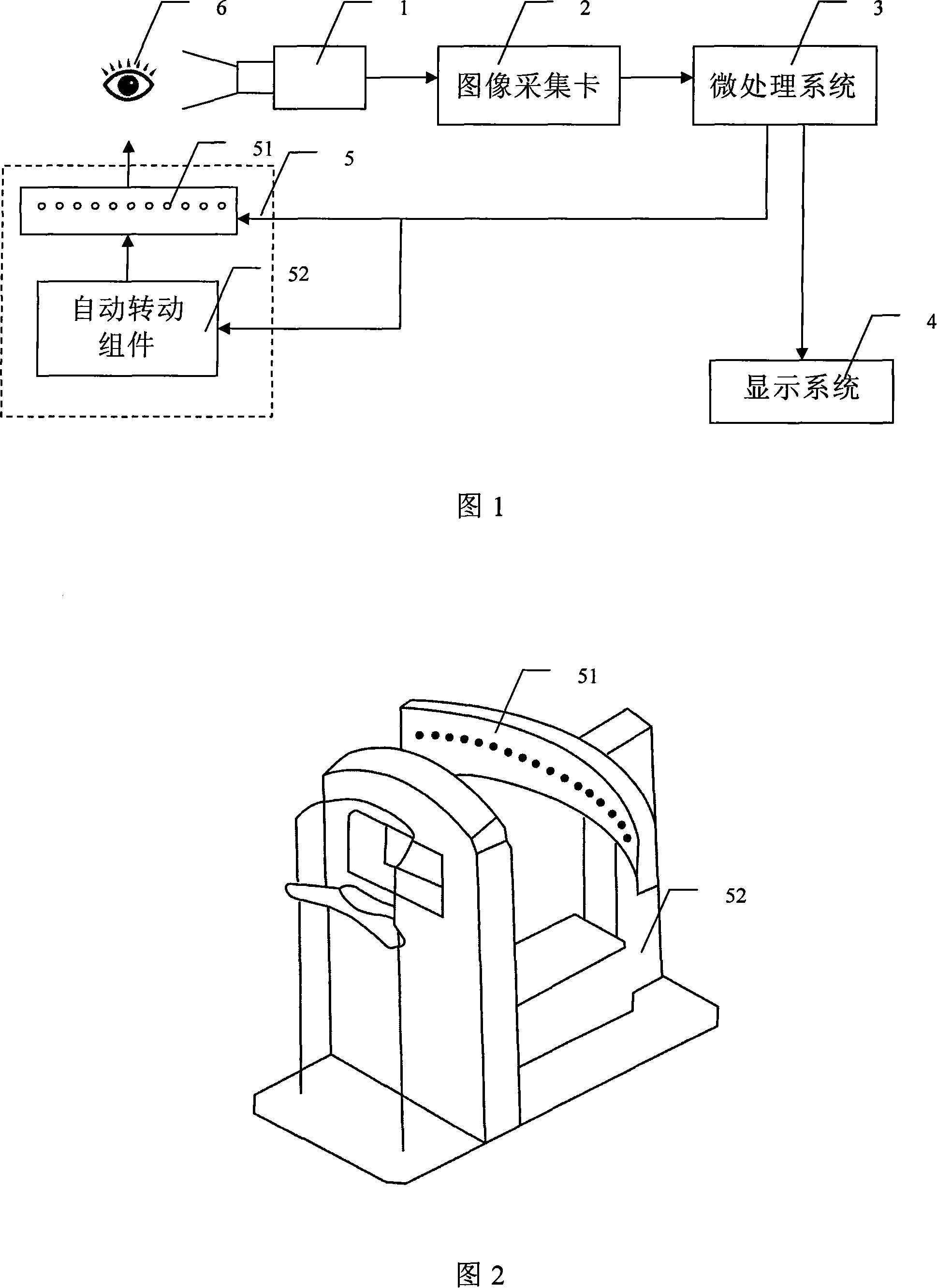
[0012] In the following, the strabismus tester of the present invention will be further described in detail in combination with specific embodiments. In the following description, when a detailed description of known functions and designs employed may obscure the subject matter of the present invention, these descriptions will be omitted here.

[0013] Fig. 1 is a schematic block diagram of a squint tester of the present invention. In the figure, the strabismus tester includes an infrared camera 1, an image acquisition card 2, a microprocessing system 3, an eyeball stimulation system 5, and an infrared filter 6. The infrared filter 6 is used to cover the gaze eye, and the eyeball stimulation signal output by the microprocessing system 3 To the eyeball stimulation system, the eyeball stimulation system provides different directions of gaze targets for the eyes;

[0014] The infrared camera 1 shoots eye movement images, and the image acquisition card 2 collects the eye movement...


PUM


Abstract

The present invention discloses a strabismus testing apparatus. It includes the following several portions: infrared camera head, image-collecting card, microprocessing system, eyeball stimulation system and infrared filter. Said invention also provides its working principle and its concrete operation method.

Description

technical field [0001] The invention belongs to the related technical field of medical instruments, in particular relates to a testing instrument for eyeballs, and specifically relates to a strabismus testing instrument. Background technique [0002] At present, there are many methods for checking strabismus, such as corneal light reflection method, multiple image inspection method, perimetry inspection method, and synoptic machine inspection method. Most of these inspection methods are subjective psychophysical inspection methods. The examiner can only observe directly with the naked eye, and can only observe the movement of one eye at a time. They cannot observe both eyes at the same time, and are easily affected by subjective factors such as the patient's cognitive ability and vision status. And produce many systematic errors. And the inspection results can only be described in words, and the movement form cannot be recorded and analyzed objectively. Contents of the in...

Claims


Application Information

Patent Timeline
IPC IPC(8): A61B3/08
Inventor 阴正勤杨红姚军平台正刘慧余涛
Owner THE FIRST AFFILIATED HOSPITAL OF THIRD MILITARY MEDICAL UNIVERSITY OF PLA
Why Eureka
Try Eureka