Offset correction circuit for voltage-controlled current source

A technology of offset correction and current source, which is applied in the direction of electric light source, electroluminescence light source, control/regulation system, etc., and can solve the problems affecting the output current of transconductance amplifier

Inactive Publication Date: 2008-03-19
ANALOG DEVICES INT UNLTD
View PDF0 Cites 13 Cited by
  • Summary
  • Abstract
  • Description
  • Claims
  • Application Information

AI Technical Summary

Problems solved by technology

[0004] However, offset voltages associated with the amplifier circuit itself may affect the output current of the transconductance amplifier

Method used


Image

  • Offset correction circuit for voltage-controlled current source
  • Offset correction circuit for voltage-controlled current source
  • Offset correction circuit for voltage-controlled current source

Examples


Embodiment Construction

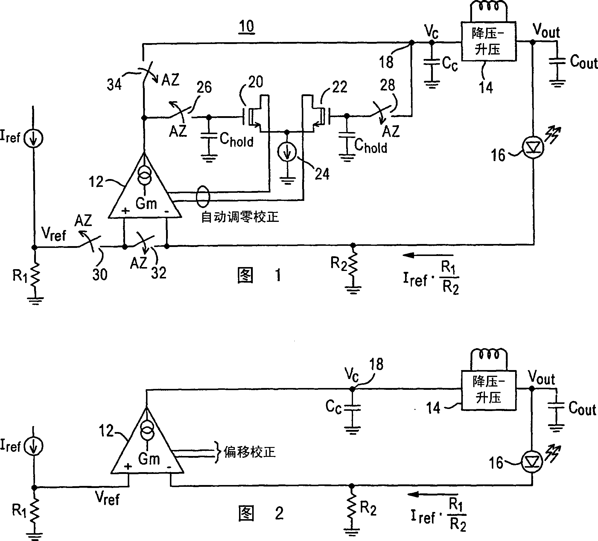
[0020] The present invention is described by taking a transconductance amplifier as an example, and the transconductance amplifier is used as an error signal amplifier in a buck-boost DC-DC converter regulation loop for a buck-boost LED driver. It should be apparent, however, that the concepts herein are applicable to any voltage-controlled current source in any power supply system.

[0021] Figure 1 shows a simplified circuit diagram showing a buck-boost LED driver 10 including a transconductance amplifier 12 as an error signal amplifier in the regulation loop of a buck-boost DC-DC converter. The output of the transconductance amplifier 12 is connected to a buck-boost DC / DC converter 14, which generates the output voltage required to drive an LED 16, eg a white LED. An example of a buck-boost DC / DC converter is the LTC(R) 3453 buck-boost converter manufactured by Linear Technology Corporation.

[0022] Specifically, the output of transconductance amplifier 12 is connected to...


PUM


Abstract

Novel circuitry and methodology are provided for correcting the offset associated with a voltage-controlled current source. An offset correction circuit is coupled to the current source to prevent the output current produced by the current source from deviating from a desired level. The current source may include a transconductance amplifier or a chopper amplifier, and may be configured to produce a zero or non-zero value of the output current.

Description

technical field [0001] The present invention relates to power supply systems, and more particularly to circuits and methods for providing offset correction of voltage-controlled current sources that can be used, for example, as buck-boost light-emitting diode (LED ) The error signal amplifier in the regulation loop of the buck-boost DC-DC converter of the driver. Background technique [0002] A voltage-controlled current source, such as a transconductance amplifier, converts the difference between voltages into a current. The ideal transfer characteristics of a transconductance amplifier are: I out =G m (V in +-V in- ), Among them, I out is the current at the output of the amplifier, G m is the transconductance, V in+ is the voltage at the non-inverting input of the amplifier, and V in- is the voltage at the inverting input. [0003] Therefore, a transconductance amplifier produces an output current proportional to the difference between the voltages at it...

Claims


Application Information

Patent Timeline
IPC IPC(8): H05B33/08G05F1/56H03F3/45H03F1/30H05B44/00
CPCH03F2203/45212H03F2203/45616H03F3/45605G05F3/20
Inventor M·R·维图尼克E·L·亨德森
Owner ANALOG DEVICES INT UNLTD
Why Eureka
Try Eureka