
Radiator fixing structure and its assembling method

A technology of fixed structure and assembly method, which is applied in the direction of instruments, instrument cooling, and instrument parts, etc., which can solve the problems affecting assembly operation time and labor costs, and achieve simplified assembly procedures and assembly time, easy assembly, and labor saving cost effect

Inactive Publication Date: 2010-05-12
DELTA ELECTRONICS INC
View PDF3 Cites 0 Cited by
  • Summary
  • Abstract
  • Description
  • Claims
  • Application Information

AI Technical Summary

Problems solved by technology

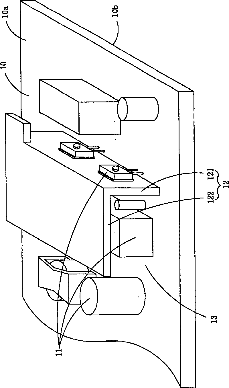
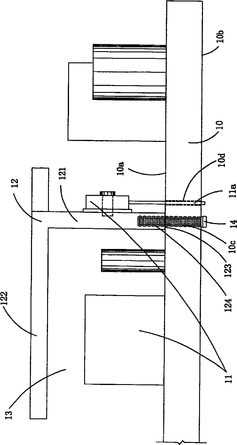
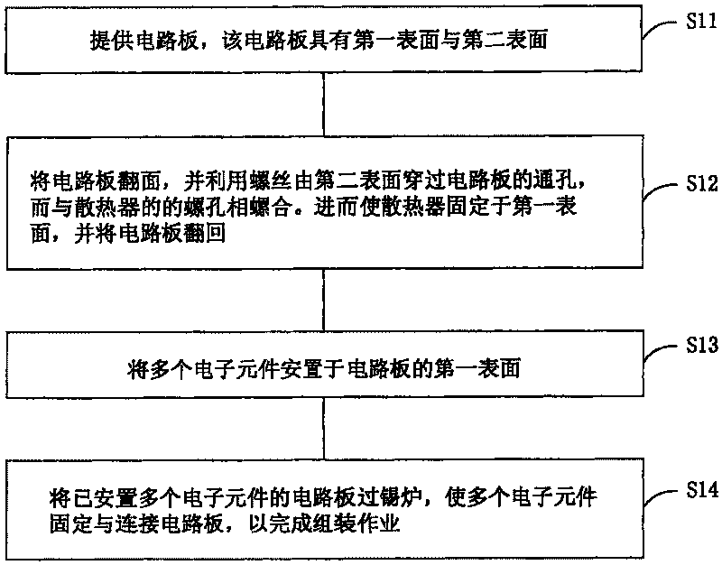
However, the traditional assembly procedure will cause the operator to turn over the circuit board 10, and the pins 11a of the electronic components 11 to be attached and fixed on the first part 121 of the heat sink 12 need to be inserted into the guides of the circuit board 10 one by one. hole 10d and lock the electronic components 11 one by one, and then go through the tin furnace, which will affect the assembly work time and labor cost

Method used


Image

  • Radiator fixing structure and its assembling method
  • Radiator fixing structure and its assembling method
  • Radiator fixing structure and its assembling method

Examples


Embodiment Construction

[0048] Some typical embodiments embodying the features and advantages of the present invention will be described in detail in the description in the following paragraphs. It should be understood that the present invention is capable of various changes in different embodiments without departing from the scope of the present invention, and that the description and drawings therein are illustrative in nature and not limiting. this invention.

[0049] see Figure 4 , which shows a schematic diagram of the radiator fixing structure of the preferred embodiment of the present invention. As Figure 4 As shown, the heat sink fixing structure of the present invention can be applied, for example, inside a power supply device to firmly fix the heat sink on the circuit board. The heat sink fixing structure of the present invention is arranged on the circuit board 20, and the circuit board 20 has a first surface 20a and a second surface 20b, wherein the first surface 20a and the second su...


PUM


Abstract

The invention is a heat dissipater fixing structure which is used for circuit board, wherein the circuit board has a first surface, a second surface and a connecting part; a plurality of electric elements are arranged on the first surface. The heat dissipater fixing structure as a minimum includes a heat dissipater arranged on the first surface of the circuit board and having a first part, a second part extending outwards from the first part, and a connecting part, at least one guide connecting part arranged on the first surface of the circuit board and having a first connecting part connectedwith and fixed onto the connecting part of the circuit board, and a second connecting part connected with and fixed onto the connecting part of the heat dissipater to fix the dissipater on the firstsurface of the circuit board. The heat dissipater fixing structure and its assembling method prevent inconvenience for operators caused by turning the circuit board during assembling operation, and can simplify the assembling procedure and reduce assembling time and labor cost.

Description

technical field [0001] The present invention relates to a heat sink fixing structure and an assembly method thereof, in particular to a heat sink fixing structure and an assembly method thereof which use an adapter device to assist in fixing the heat sink on a circuit board. Background technique [0002] Radiators have been widely used in various electrical equipment to help solve the problem of heat dissipation inside the electrical equipment. For example, various heat sinks are usually arranged on the circuit board inside the power supply device to transfer the heat generated by the electronic components on the circuit board to the housing to dissipate heat when the power supply device is running. However, as the power of the power supply device increases, the heat sink also develops towards reducing the thermal resistance and increasing the heat dissipation area, so heat sinks of various shapes are produced accordingly, so how to fix various heat sinks on the circuit boar...

Claims


Application Information

Patent Timeline
Patent Type & Authority Patents(China)
IPC IPC(8): H05K7/00H05K7/20G12B15/00
Inventor 游文龙
Owner DELTA ELECTRONICS INC
Learn More