


Quick Research
Generate reliable direction feasibility study reports for your R&D in just a few steps.

Technical Q&A
Discover and master advanced knowledge NOW. Basics, ideas, possibilities, all at once.

Find Solutions
As an expert in R&D theories, this can generate solutions to your technical problems instantly.

Evaluate Feasibility
Analyze your overall solution with one click, know your potential R&D risks in advance.

Monitor Landscape
Get weekly tech updates, stay abreast of the latest tech innovations and key insights.
Expansion gate
A technology for retractable doors and door frames, which is applied in the direction of gates/doors, door/window accessories, buildings, etc., which can solve the problems of high maintenance costs, insufficient door body movement stability, and high technological conditions for track laying, and achieve convenient maintenance and stability High, accurate mobile positioning effect
- Summary
- Abstract
- Description
- Claims
- Application Information
AI Technical Summary
Problems solved by technology
Method used
Image

Examples
Embodiment 1
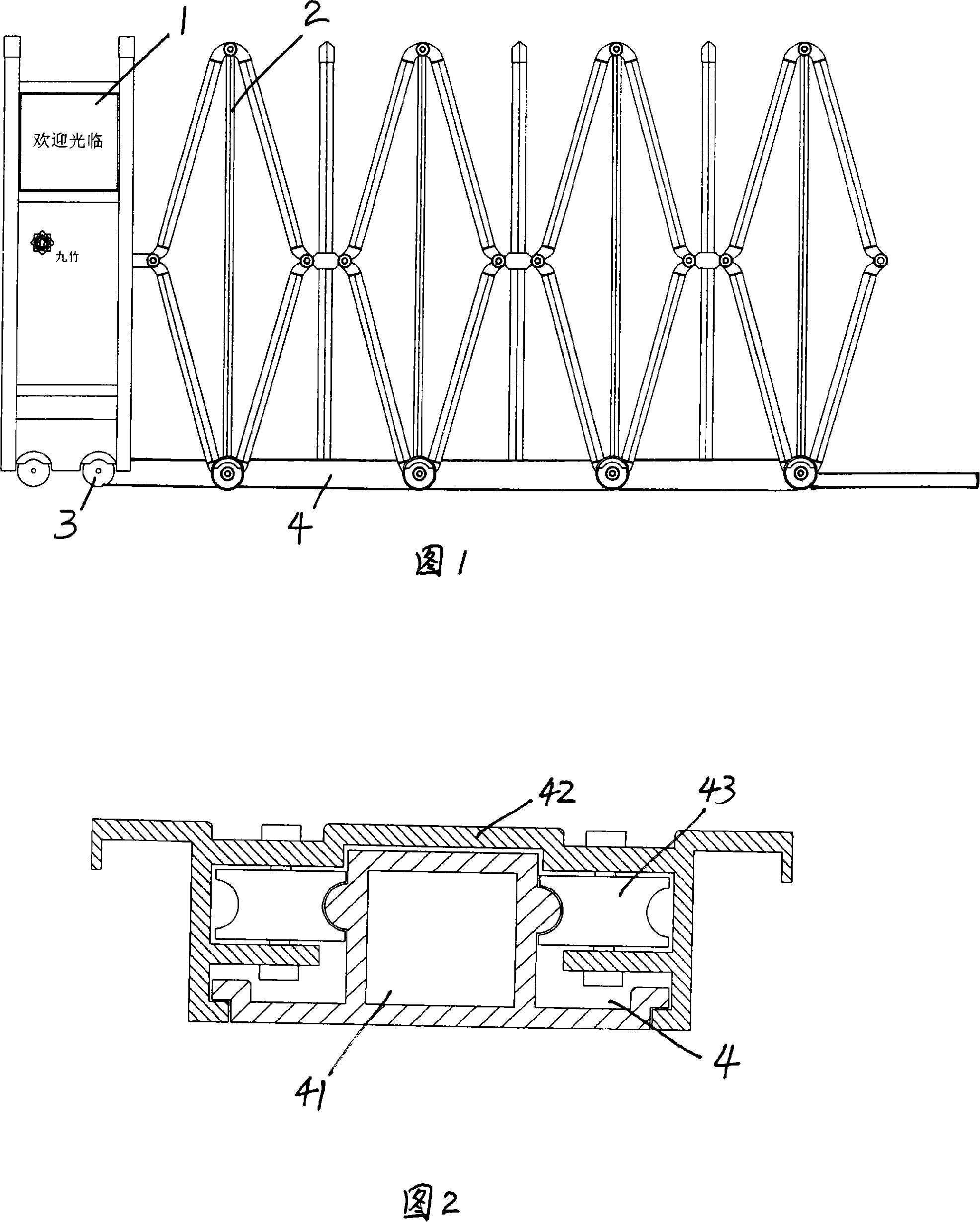
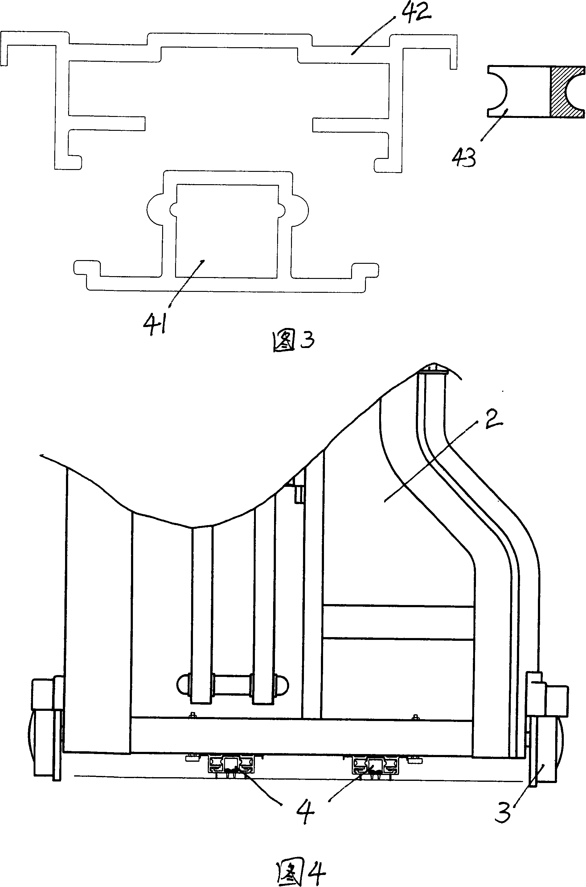
[0022] As shown in Figure 1, it is a schematic diagram of the overall structure of this embodiment. The retractable door of this embodiment includes a door head 1, a door frame 2 and walking wheels 3, wherein the door head 1, door frame 2 and walking wheels 3 are similar to ordinary telescopic doors. Walking wheel 3 is installed on door head 1 and door frame 2 bottoms. The door frame 2 is composed of several door rows. Two mother-child slide rail devices 4 are installed in the lower part of the door frame 2 in parallel. One end of each mother-child slide rail device 4 is fixed on the ground, and the other end is fixed at the joint between the door head 1 and the door frame 2. . The door frame 2 is expanded or contracted through the motion guidance of the mother-to-child slide rail device 4. The mother-to-son slide rail device 4 includes: a mating mother part 42, which is used to guide and accommodate the inserted sub-parts, so that the door frame can be kept in the correct sta...
Embodiment 2
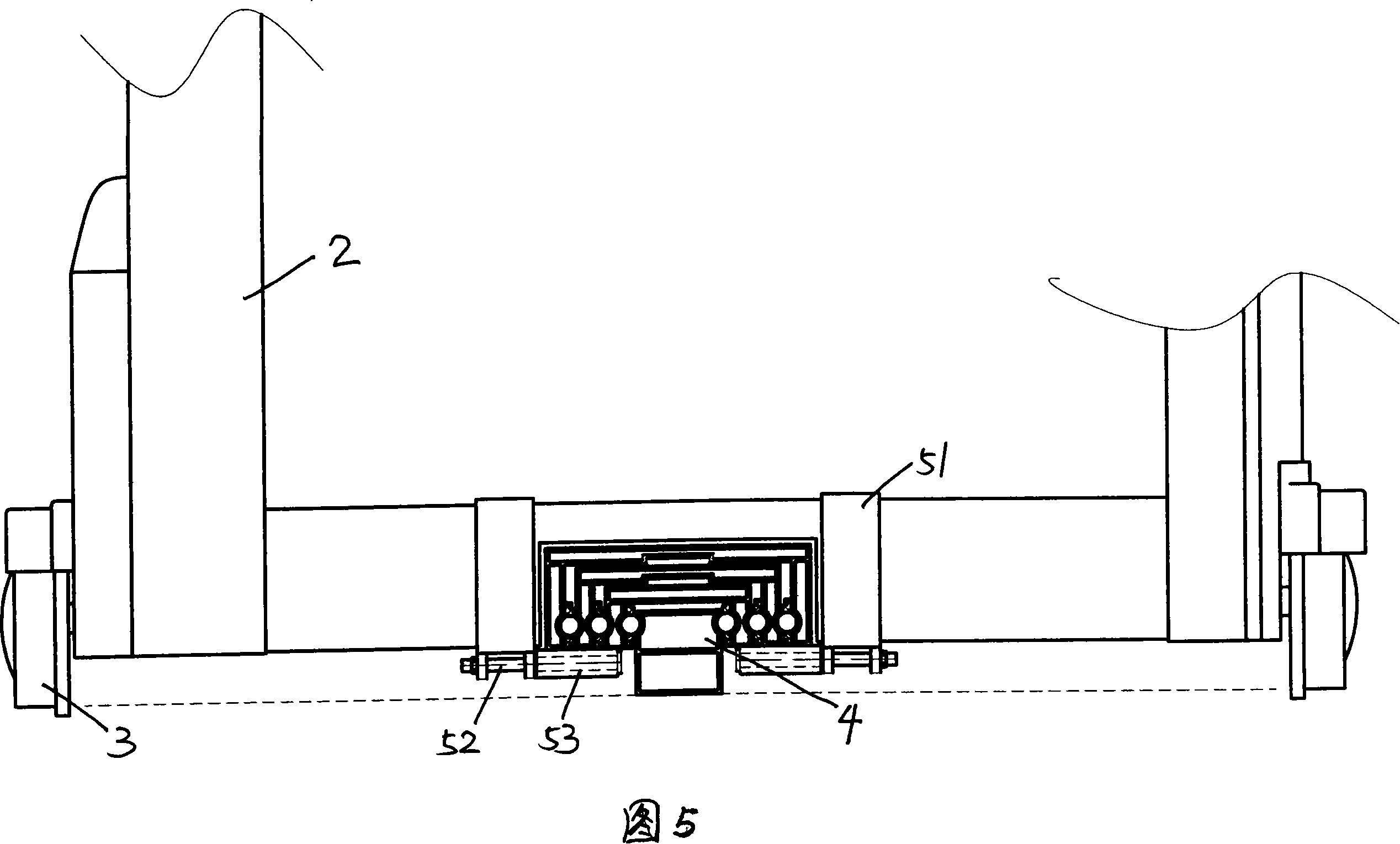
[0024] As shown in Figure 5, it is a schematic diagram of the local structure after telescopic assembly of this embodiment. The telescopic door of this embodiment includes a door head 1 (not shown in the figure), a door frame 2 and walking wheels 3, wherein the door head 1, door frame 2 Similar to the common retractable door with the traveling wheel 3, the traveling wheel 3 is installed on the door head 1 and the door frame 2 bottoms. In addition, a mother-child slide rail device 4 is also installed at the bottom of the telescopic door in this embodiment. The mother-child slide rail device 4 is composed of an embedded sub-piece 41, a small fitting mother part 45, a middle fitting mother part 47, a large fitting mother part 42 and several sliding balls 44, and the sliding balls 44 pass through the sliding plate 440 are embedded at intervals between the inserting sub-piece 41 and the small fitting female part 45, between the small fitting female part 45 and the middle fitting fe...
Embodiment 3
[0027] This embodiment is similar to Embodiment 2, the difference lies in that the mating mother parts of the mother-child slide rail device 4 are directly and smoothly matched without sliding balls. In this way, the process can be simplified and the cost can be saved. In addition, the limit block 5 is composed of a Π connecting frame 51, a rotating connecting column 52, a wear-resistant sleeve 53 and a roller 54, and the roller 54 is installed on the bottom of the Π connecting frame 51. Such a structure increases the stability of the telescopic door when it moves. The principle is the same as in embodiment 2.
[0028] Fig. 8 is a schematic diagram of component assembly of the mother-child slide rail device and the limit block in this embodiment.
PUM
 Abstract
Description
Claims
Application Information
 - R&D Engineer
- R&D Manager
- IP Professional
- Industry Leading Data Capabilities
- Powerful AI technology
- Patent DNA Extraction
Browse by: Latest US Patents, China's latest patents, Technical Efficacy Thesaurus, Application Domain, Technology Topic, Popular Technical Reports.
© 2024 PatSnap. All rights reserved.Legal|Privacy policy|Modern Slavery Act Transparency Statement|Sitemap|About US| Contact US: help@patsnap.com