Eureka AIR delivers breakthrough ideas for toughest innovation challenges, trusted by R&D personnel around the world.

Sleeve spot welding machine facilitating blanking

A spot welding machine and blanking technology, which is applied in welding equipment, welding equipment, auxiliary welding equipment, etc., can solve the problems affecting the effect of sleeve spot welding, the clamping force of the clamping plate is large, and the spot welding accuracy is not high. Achieve good welding effect, good clamping effect and convenient operation

Active Publication Date: 2019-09-10
DEZHOU LINGCHENG POWER SUPPLY CO OF STATE GRID SHANDONG ELECTRIC POWER CO
View PDF7 Cites 0 Cited by
  • Summary
  • Abstract
  • Description
  • Claims
  • Application Information

AI Technical Summary

Problems solved by technology

[0006] Most of the existing sleeve electric welding machines use two clamping blocks to clamp the two ends, one clamping plate is fixed, and the other clamping plate can be moved, and the sleeve is prone to rotate during the spot welding process. , the accuracy of spot welding is not high, and at the same time, the clamping force of the clamping plate is too large, resulting in deformation of the sleeve, which greatly affects the effect of spot welding of the sleeve, and the clamping block needs to be cut Move away, unloading is inconvenient

Method used


Image

  • Sleeve spot welding machine facilitating blanking
  • Sleeve spot welding machine facilitating blanking
  • Sleeve spot welding machine facilitating blanking

Examples


Embodiment Construction

[0036] In order to enable those skilled in the art to better understand the technical solution of the present invention, the present invention will be described in detail below in conjunction with the accompanying drawings. The description in this part is only exemplary and explanatory, and should not have any limiting effect on the protection scope of the present invention. .

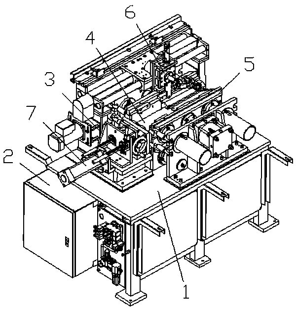
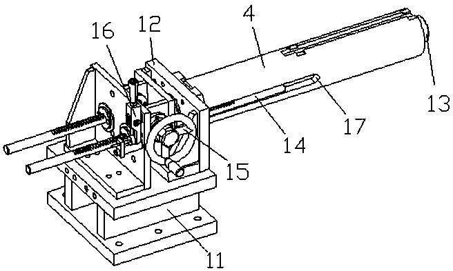
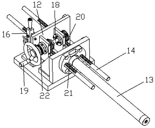
[0037] Such as Figure 1-Figure 10 As shown, the specific structure of the present invention is: a sleeve spot welding machine for convenient blanking, which includes a frame 1 and a power distribution control box 2, and the frame 1 is provided with a location that cooperates with the sleeve 4 Device 3, the clamping mechanism 5 that cooperates with the front and rear sides of the sleeve 4 on the positioning device 3 and the welding mechanism 6 that cooperates with the upper part of the sleeve 4 on the positioning device 3. The positioning device 3 includes a Bearing 11, described bearing 11 is provide...


PUM


Abstract

The invention relates to a sleeve spot welding machine facilitating blanking. The sleeve spot welding machine comprises a rack and a power distribution control cabinet, wherein a positioning device matched with a sleeve, a clamping mechanism and a welding mechanism are arranged on the rack; the positioning device comprises a support arranged on the rack; two positioning seats are arranged on the support; a positioning inserting shaft matched with the sleeve is arranged on the outer side of one of the positioning seats; a positioning ejection rod matched with a matching groove in the side faceof the sleeve is further mounted on each of the positioning seats and is tangent and matched with the upper and lower surfaces of the matching groove; and the positioning ejection rod is matched withan ejection rod movable device arranged on each of the positioning seats. According to the sleeve spot welding machine, the clamping mechanism matched with the side face of the sleeve is adopted for clamping, and the positioning ejection rods matched with the matching groove is adopted to position the sleeve, so that the situation that the sleeve rotates is avoided, the sleeve is prevented from deviating during the spot welding process, the spot welding precision is improved, and blanking of the sleeve is facilitated.

Description

[0001] Original application number: 2017107266353 [0002] Date of original filing: August 22, 2017 [0003] Applicant of the original case: Dongguan Ronggong Automation Technology Co., Ltd. technical field [0004] The invention relates to the field of sleeve processing equipment, in particular to a sleeve spot welding machine which is convenient for blanking. Background technique [0005] Sleeves are commonly used parts with a wide range of applications. Spot welding is sometimes required during processing, and axial matching grooves 17 are provided symmetrically on the sides of some sleeves to meet different needs. [0006] Most of the existing sleeve electric welding machines use two clamping blocks to clamp the two ends, one clamping plate is fixed, and the other clamping plate can be moved, and the sleeve is prone to rotate during the spot welding process. , the accuracy of spot welding is not high, and at the same time, the clamping force of the clamping plate is to...

Claims


Application Information

Patent Timeline
Patent Type & Authority Applications(China)
IPC IPC(8): B23K31/02B23K37/00B23K37/02B23K37/04
CPCB23K31/02B23K37/00B23K37/0247B23K37/0435
Inventor 邓君杨坤
Owner DEZHOU LINGCHENG POWER SUPPLY CO OF STATE GRID SHANDONG ELECTRIC POWER CO
Why Eureka
Eureka Blog
Learn More