Built-in push-button switch for dust remover

A technology for vacuum cleaners and electrical switches, which is applied to vacuum cleaners, cleaning equipment, household appliances, etc. It can solve the problems of misoperation of vacuum cleaners, not being exposed outside the casing, and easy to be touched by mistake, so as to avoid the effect of being easily touched by mistake

Inactive Publication Date: 2008-03-19
LG ELECTRONICS (TIANJIN) APPLIANCES CO LTD
View PDF0 Cites 6 Cited by
  • Summary
  • Abstract
  • Description
  • Claims
  • Application Information

AI Technical Summary

Problems solved by technology

[0010] Aiming at the problem that the upper end of the switch of the vacuum cleaner in the prior art is exposed outside the casing, it is easy to be touched by mistake and misoperation of the vacuum cleaner occurs. The present invention introduces a vacuum cleaner with a built-in switch. In the groove on the upper edge of the casing, and the groove is covered by the handle placed on the upper edge of the casing, so that the switch button on the upper end of the switch cannot be exposed outside the casing. mishandling problem

Method used


Image

  • Built-in push-button switch for dust remover
  • Built-in push-button switch for dust remover
  • Built-in push-button switch for dust remover

Examples


Embodiment Construction

[0025] The specific embodiment of the present invention will be further described in conjunction with the accompanying drawings.

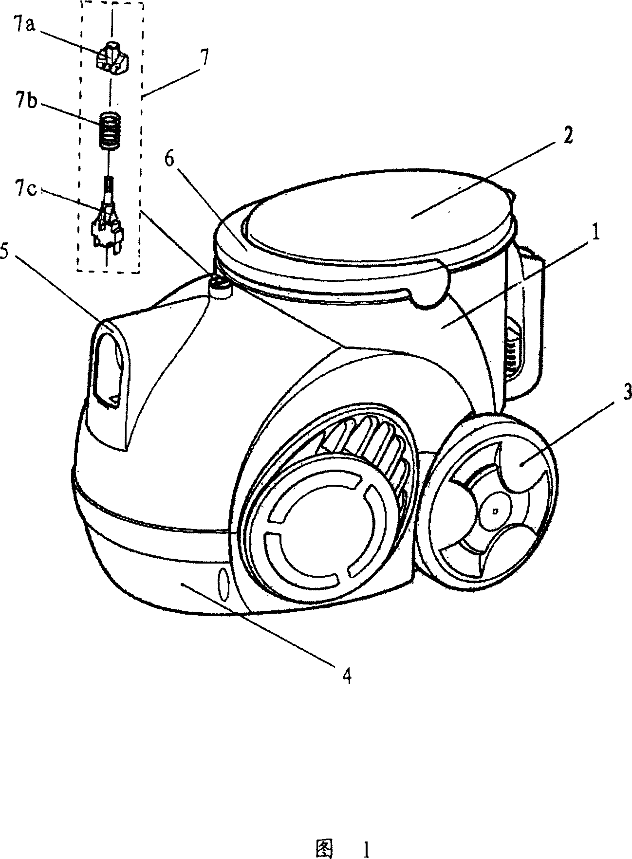
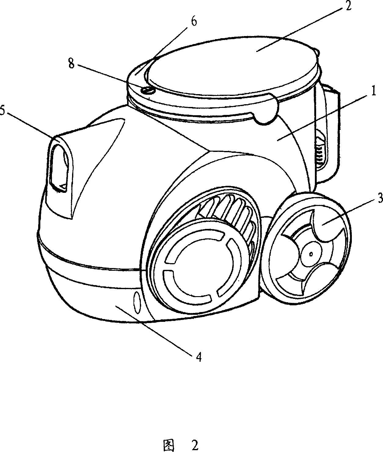
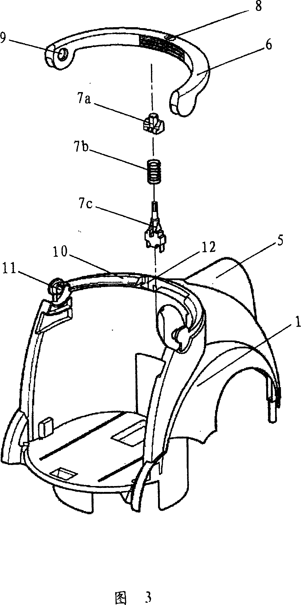
[0026] Fig. 2 shows the appearance of the main body of the vacuum cleaner according to the present invention, and Fig. 3 shows an exploded view of the shell of the vacuum cleaner according to the present invention and its built-in key switch.

[0027] As shown in the figure, the appearance of the vacuum cleaner body involved in the present invention is mainly composed of a front casing 1 and a dust collecting barrel 2 arranged at the rear of the casing. Rollers 3 are installed on both sides of the casing 1, and the bottom is a base 4. The handle 6 is installed on the upper edge 10 of the casing 1, and the insertion holes 9 at both ends of the handle 6 are sleeved on the protrusions 11 inside the two ends of the upper edge 10 of the casing, and the handle 6 can be rotated. When the handle 6 is placed on the casing 1, the upper edge 10 of the casing...


PUM


Abstract

The invention relates to a inside laid keyswitch of a dust collector, which is arranged inside a groove at the edge of a machine crust and consists of a keyswitch, a spring and an electric appliance switch plug-in which are assembled together. The top of a switch key at the upper part is lower than the upper edge of the groove; the electric appliance switch plug-in at the lower part is opposite to a contact unit at an external power source wire of a motor inside the machine crust. The groove of the inside laid switch at the edge of the machine crust is covered by a handle which is arranged at the edge of the machine crust, which ensures that the switch component can not be shown outside the machine crust, so as to avoid the problems that the switch is touched by mistake and the dust collector is operated by mistake. When the dust collector needs starting, the handle is lifted and rotated from the position which is adhibited with a switch mark, and the groove which is covered by the handle is shown out, and then the switch key of the switch is pressed, and the switch key presses the electric appliance witch plug-in by the spring to switch on an external power source circuit of the motor inside the machine crust, and the dust collector can run.

Description

technical field [0001] The invention relates to a vacuum cleaner, in particular to an electrical switch of the vacuum cleaner. Background technique [0002] The vacuum cleaner is a household appliance for indoor cleaning and hygiene, which is used to remove dust from the ground, carpets, walls, furniture and various gaps. Generally speaking, the components of the vacuum cleaner mainly include the main body of the vacuum cleaner, the suction head and the suction pipe, etc. The suction device mainly formed by the motor and the fan is arranged in the main body. The tube communicates with the inside of the main body. After the power is turned on, the motor drives the impeller of the fan to rotate at a high speed, exhausting the air in the vacuum cleaner, forming an instantaneous vacuum in the vacuum cleaner, and forming a relatively high negative pressure difference with the outside atmosphere. Under the action of this negative pressure difference, the garbage and dust near th...

Claims


Application Information

Patent Timeline
Patent Type & Authority Applications(China)
IPC IPC(8): A47L9/00
Inventor 李艳君
Owner LG ELECTRONICS (TIANJIN) APPLIANCES CO LTD
Why Eureka
Try Eureka